Kickstarter Fulfillment Workspace and Jigs
February 25, 2022
Blog
I’m currently just over halfway through fulfillment on the JC Pro Macro 2 keypad kickstarter project. 178 people pledged with the expectation of a reward, meaning that putting a bit of time and thought into my fulfillment workspace at the beginning was an excellent use of time and resources.
The Goal: Manage Complexity
My JCPM 2 device, which is now available for pre-order on Tindie, requires about 20 different parts to put together properly, and during this early 2020s parts shortage-era I was glad to be able to obtain them without difficulty. The devices are shipped as bare boards with LEDs (easy), kits (harder), and fully assembled and programmed (hardest). The fully assembled boards, however, have the advantage that I can fully check them before being being boxed up. Kits could be prone to mistakes if I didn’t set things up correctly.
To help ensure people got what they expected, I set my process up so that a number of smaller parts are placed into a baggie as a hardware kit. These can then be deposited into a final assembly with the larger parts. Different options would require slightly different small hardware setups, so to simplify things, I included the required bits for any device. This saves packing time and cuts down on the potential for errors.
It was also very helpful to get my PCB/PCBA supplier PCBWay to check that LEDs were soldered on and working properly before they sent them to me. This allowed them to correct any errors in-house, and meant that I didn’t have to connect and check that everything was blinking. It’s a small thing, but when doing something hundreds of times, every little process adds up.
Fulfillment Rack

Image Credit: Jeremy Cook
To keep all parts within easy reach, I constructed a rack/bin system with ZYLtech 2020 and 2040 (20mm x 20mm/40mm) aluminum extrusion that I had on-hand. Such extrusion can be somewhat expensive, but it’s easy to set up, and when I need to break down my setup, it can then be reused for other purposes. It consists of two uprights, along two horizontal members on which bins are attached using 3D-printed French cleat-style hangers.
On top of everything, a third horizontal member holds a shelf that I cut out on my laser, supported in part by 3D-printed angle brackets that I modified from another design. This shelf often holds my laptop, as well as boxes of work-in-progress.

Image Credit: Jeremy Cook
After some experimentation, I settled on an options bin section on the left (top and bottom), a small components area with parts that are combined into hardware kits (top right), and a large components/kit area (bottom right). I didn’t have this arrangement figured out to begin with, so it’s very helpful that the bins can be easily rearranged. I used different colors for the bins to help with quick visual identification.
To assemble a JCPM 2 kit, I take an item from each bin in the bottom-right section and stuff it in a box. I can then move on to options, though lately I’ve been reversing the options/standard order to help with accuracy. To make up the parts kit, I do a similar procedure with the top right area, paying attention to number of parts from each bin, since some parts need more than one each. Labels are applied to help with the picking process.
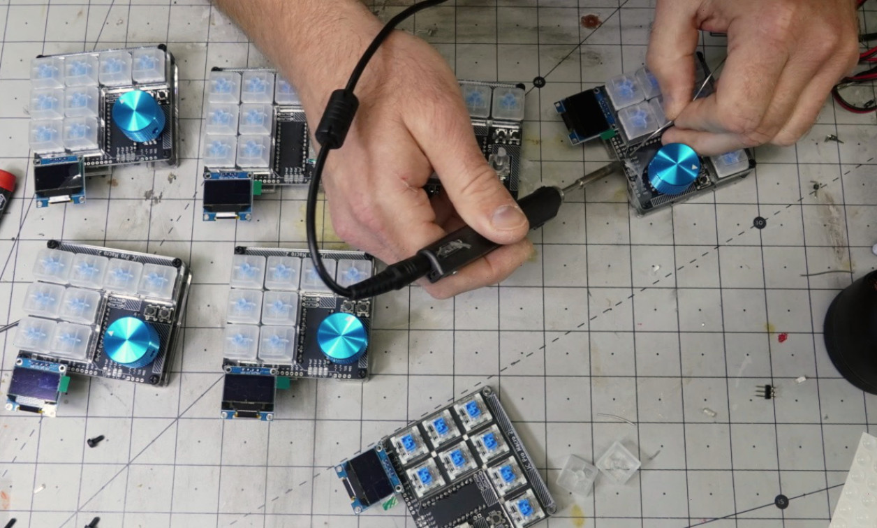
3D-Printed Jigs


Image Credit: Jeremy Cook
Along with pick bins, the other element to my manufacturing cell setup was creating 3D-printed assembly jigs. These went through many…many iterations, but I ended up with a jig that holds to-be-soldered elements in place on the board, along with a second jig that makes it easier to solder up the Pro Micro board that powers the JCPM 2. Suffice to say, that without such jigs, the process would be much harder and the end product would feature parts that were not as well aligned.
For another example 3D-printed solder jibs, I used one put together “light cubes” in this post. Jigs, of course, aren’t anything new, but 3D-printing gives you flexibility and ease-of-manufacturing that would be difficult with other processes. On the other hand, making fine adjustments often means re-printing the whole assembly. When working with metal in a more traditional sense, you might simply have to take a few thousandths of an inch off here of there to make things perfect.
That being said, it’s amazing what one can do with garage-based equipment, plus a bit of help from contract PCB/PCBA assembly. I explain my setup in the video below, along with a time lapse of it in use at the end:
Jeremy Cook is a freelance tech journalist and engineering consultant with over 10 years of factory automation experience. An avid maker and experimenter, you can follow him on Twitter, or see his electromechanical exploits on the Jeremy Cook YouTube Channel!