How Not to Build a Custom RP2040 Dev Board
October 10, 2023
Blog
In Part 1 of this custom RP2040 board series, I discussed how to build your own RP2040 dev board, and why you’d want to do so. While the process seems more straightforward to me after successfully going through it, there are many ways that a board can fail, whether through a faulty design, poor assembly, or both.
This blog will document a few things that you shouldn’t do when creating a custom RP2040 dev board. My first attempt at this was, in fact, a failure. On the other hand, it led to what I consider a much better design that I can hopefully build upon and reuse in the future.
Keep Things Simple
(1).png)
Image Credit: Screencap, Jeremy Cook
For my first RP2040 board, I decided to add audio-output functionality. While testing out two things at the same time would seem efficient, it may have been better to simply concentrate on the fundamental board architecture, and blinking an LED or two. My second dev board design does integrate “bonus” battery/USB switching capability, but I’ll grant myself an exception to this rule here, as that was fairly simple and it worked quite well.
Minimize and Standardize Small Components
While not always possible, I used only one type of 0603 capacitor (100nF), and one type of 0603 resistor (27Ω) on my latest design. While there weren’t a huge number of different components on the original board, minimizing them made things much easier.
Of course, there are smaller components available (e.g. 0402) that may be advantageous in some circumstances. For hand assembly, however, bigger is often better.
Buy More Small Components Than You Need
With surface-mount components often supplied in sub-grain-of-rice package sizes, you’re bound to drop a few on the floor. At less than a cent for many of these components, looking around for them is not worth your time, and the risk of mixing parts is unacceptable. For these reasons, be sure to have a few (dozen) extra on-hand during assembly.
Don’t Forget the Solder Stencil
When I ordered my first board from PCBWay, I forgot to order a solder stencil. I wasn’t trying to save money, as the time and frustration savings are worth far more to me than the stencil’s ~$10 price tag. I simply didn’t think of it at the time. While I can’t say that was the reason my first board didn’t work, it certainly didn’t help.
On the other hand, I could have manufactured a solder stencil on my laser cutter. This may have been a better solution than trying to glop solder paste under the RP2040 microcontroller:
Don’t Leave Solder Bridges
As shown in the video below, it is possible to attach the RP2040 without a solder stencil. On the other hand, it doesn’t actually show the board blinking away after this build process. What it does show, just after the 19:00 mark, is that solder can form unwanted connections (bridges) on RP2040 pins. This can be rectified with solder, flux, and a soldering iron. The video also features a pre-heater which seems to make things easier.
Note that solder bridges can occur in other parts with close pad spacing, for example USB connectors. After the soldering process, be sure to check for bridges using a loupe or microscope.
Don’t Test With Critical USB
This I did correctly. I plugged my initial board into an expendable wall wart USB power supply, allowing it to draw way too much current and heat up, while not risking my computer ports. I even used a USB cable with a little wattage monitor that further told me something was wrong. The board was a failure, but my other equipment was preserved.
For my successful board, I again plugged it into an expendable USB supply. When nothing seemed amiss, I tested that the power supply was emitting the expected voltage and poked around on the RP2040’s capacitors. All was well this time.
Do Ask for Help
Per my two Tweets (Xs?) below, people are extremely willing to share their opinions on your board design. It takes some skill and/or educated guessing to filter out the good from the bad, but I believe the feedback I got back as a result improved my revised design immensely.
Designing a @Raspberry_Pi RP2040 board. Question is, do I need to do differential pair routing between USB and chip as it's only ~6mm? Seems like making the transition might be more trouble than its worth from a signal and effort perspective. pic.twitter.com/z795JOLt47
— Jeremy Cook 🤖 (@JeremySCook) July 25, 2023
Trying to make a circuit that cuts off 9V battery source when USB power is plugged in. What's below seems incorrect, considering options.
— Jeremy Cook 🤖 (@JeremySCook) July 13, 2023
Maybe an N-channel depletion MOSFET on the GND line to the battery? Maybe there's a standard way to do this? pic.twitter.com/Zi1h6skOWE
As noted in Part 1, the revised board design is available here. I welcome your feedback via the methods listed below, or you can email me: [email protected].
Don’t Not Get Started
Most likely my initial design will never blink an LED or play music as envisioned. At the same time, it allowed me to experiment with the design and work out a number of techniques that ultimately led to my functional RP2040 board.
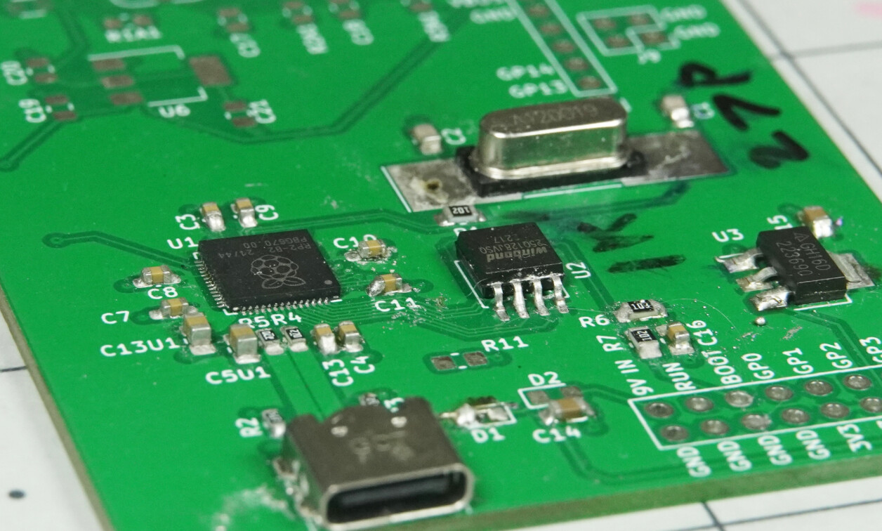
.jpg)
Image Credit: Jeremy Cook
Realistically, it took me many hours of work to produce this successful board, so one should consider whether it’s worth your time to pursue a custom design. On the other hand, I now have the experience and confidence to do this again, and a standard design and set of components that can hopefully be reused going forward.
Of course, once you have your custom dev board functional, you’ll need to set it up properly software-wise to get the most out of it. I’ll go over how to do so in the context of CircuitPython in part 3.