Hands-On With CAN Bus
September 29, 2023
Blog
When implementing device-to-device communications you have a choice of various protocols, such as SPI, I2C, or UART. Each of those is appropriate for board-level and/or short-distance, low-speed communications. Often overlooked in some circles–though used widely in others–the CAN (Controller Area Network) protocol presents a number of compelling advantages.
Released by Bosch at the 1986 Society of Automotive Engineers conference in Detroit, Michigan, CAN is now the prevailing standard for intra-vehicle device communications. Perhaps unsurprisingly, it’s also widely used in industrial automation equipment, producing (among other things) cars that use this same protocol.
CAN Bus is able to transmit using differential signaling at 1 Mbit/s at up to 40m, and up to 1000m at reduced data speeds. There is no master device per se, and arbitration is instead taken care of by a lossless message priority scheme. This topology means that no one device is critical to the overall operation of the bus.
.jpg)
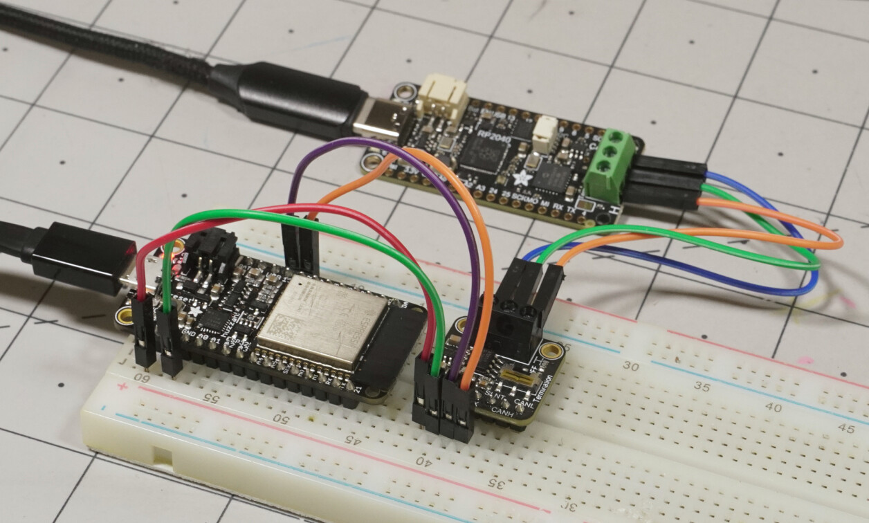
Caption: The simple two-device CAN network used in example 2
Image Credit: Jeremy Cook
CAN Costs
CAN requires specialized hardware to communicate over a CAN bus–a controller that works with the protocol, and a transceiver that physically interacts with the bus. Some microcontrollers, such as the ESP32 and STM32F405 have the controller/protocol built-in, allowing them to use a transceiver directly, e.g. NXP’s TJA1051. Others will need an external controller and a transceiver to communicate via CAN. Microchip’s all-in-one MCP25625 chip takes care of both functions, and communicates with a microcontroller or other computing device via SPI.
On a consumer level, broadly expect to tack on a dollar for the TJA1051, or three bucks for the MCP25625, plus the requisite layout complications. While this is cost-prohibitive in some situations, in industrial automation and automotive (especially at large scales) the extra expense is a small price to pay for increased reliability. That being said, if you need simple, robust, and wired messaging over 10s or even 100s meters, CAN deserves consideration. As for how to get started, read on.
Example 1: CAN Loopback (Sans Wiring Loop)
For our first CAN demo, we will use a single Adafruit RP2040 CAN Bus Feather. This uses an MCP25625 chip to communicate via CAN, interfacing directly with the RP2040 via SPI. The CAN transceiver sets CAN-L and CAN-H outputs to individual dominant and recessive voltages, which together create a large or small voltage differential between the two (typically +2V and ~0V).
At the same time, the transceiver monitors the resulting bus voltage differential, performing a loopback test with no external hardware or wiring. Just run the CircuitPython code in the Simple Test Example found here, and you can test whether your device is sending and receiving signals on this “network of one.”
Example 2: Device-to-Device Communication
(1).png)
Image Credit: Jeremy Cook
As interesting as talking to yourself might be, the real magic of any protocol is communication between multiple devices. Another example from the above-linked page allows two identical RP2040 CAN Bus Feathers to talk, wired as shown above. I suggest changing the actual messages sent between the two, and even physically marking the devices, to keep track of the message origin.
Example 3: ESP32 CAN to RP2040 CAN Bus Feather
To illustrate how well CAN... can talk between different devices, I fished out an older Huzzah32 Feather from my parts repository. Having an ESP32 onboard, it can is able to speak CAN natively, only requiring the transceiver element. I used the CAN Pal TJA1051T/3 breakout for this job, with the Huzzah32's 3.3V output and ground connected, and D13/D12 wired to transceiver Rx/Tx.
(2).jpg)
Image Credit: Jeremy Cook
For various reasons, setting up the Huzzah32 to work with CircuitPython required a bit of yak wrestling. However, the actual communication between the two boards was refreshingly simple. CAN-H to CAN-H, CAN-L to CAN-L, GND to GND, with no real consideration of the baud rate. With a bit more digging into the microcontroller side of things and message formatting, it would likely be an excellent way to coordinate two devices. My rather rough code modifications are up on GitHub.
More You CAN Do
Here I’ve presented several examples to help start your CAN journey. For another idea, check out this handy packet monitor by Technoblogy’s David Johnson-Davies, using an Adafruit ESP32 Feather, TFT display, and TJA1051 CAN Bus Transceiver. You also might consider making an extra gauge or three for your vehicle via its CAN-based OBD2 port, as illustrated in this build.
Finally, if you want to delve more deeply into how the protocol itself works and its proper setup, this Circuitstate article has some really good information. While CAN isn’t always the preferred communication solution, it presents some big advantages for robust hard-wired communication beyond a few meters.