Analog Capacitive Sensing With PCB Traces
July 19, 2023
Blog
Capacitive touch sensing, as discussed in my “RP20-Footie” post, as well as in class 6 of my Developing with Pi series, can be a great way to turn things on and off at a moment’s notice. But what about using a capacitive input as an analog device, such as a slider?
There are, in fact, a number of ways to accomplish this. For more background on capacitive sensing in both digital and analog realms, I’d recommend checking out Microchip’s Capacitive Touch Sensor Design Guide. Starting on page 9, it talks about using multiple capacitor pads as a slider, and interpolating between many pads for better resolution. It also shows how to use an angled design to facilitate interpolation, as well as how to configure pads in a wheel.
In this experiment, I’ll explore whether I can reasonably use GPIO pins to sense differences in position based on a relative contact area between one’s finger and PCB traces. This makes things simple from a PCB design point of view, as I didn’t need to construct any custom pad shapes.
Experiment
.png)
Image Credit: Jeremy Cook
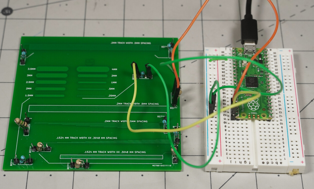
I created a number of traces in two main styles:
-
5-Line “Ladder” Configuration
- Starting at 1.5mm trace width, adding .5mm to each successive trace up to 3.5mm width
- Starting at .25mm trace width, multiplying by 2 for each successive trace up to a 4mm width
- “Line Graph” Configuration–Lines progressively drop off based on distance from the connection, reducing overall contact area.
- .2mm track width, .5mm center-to-center spacing
- .2mm track width, .5mm center-to-center spacing (ground plane underneath)
- .1524mm track width, .3048mm center-to-center spacing
A Raspberry Pi Pico running this CircuitPython code was used for capacitive sensing averaging 10 readings together in an attempt to alleviate noise. A 1.6mm thick circuit board (design available here) was used for capacitive traces with a 1MOhm resistor tied to ground and connections made with DuPont-style connectors.
Results – Interesting, but Useful?
.png)
Caption: Raw capacitive values / Image Credit: Jeremy Cook
.png)
Caption: Averaged capacitive values in steps–still significant noise / Image Credit: Jeremy Cook
In each case, less total contact area generated less capacitive input. In the ladder and larger line graph configurations, one can reasonably pick out roughly five states. I didn’t notice a difference between having a ground plane and not having one. The smaller (.1524mm trace) configurations yielded results that were similar, though seemed to be slightly reduced in magnitude.
The problem with these configurations is that even with averaging there is a significant variation and noise in the response to a finger press. A certain area might nominally be a 3 out of 5, but this can easily vary higher and lower based on how hard one is pressing down. I also suspect different people would have their own individual capacitance effects.
The design guide referenced earlier would be a good place to start if you wanted to attempt to continue with this work. Either way, the how hard are you touching? issue will need to be addressed.
More Ideas
New capacitive touch idea. Seems maybe I heard that electronic calipers work using a similar principle on the @TheAmpHour Podcast pic.twitter.com/EBK3e7IxXr
— Jeremy Cook 🤖 (@JeremySCook) July 17, 2023
While my trace experiments didn’t produce the consistency I’d hoped for, one interesting effect is that you can effectively read how hard someone is pressing. In fact, it would be quite reasonable to construct a capacitive input with both soft and hard press settings. While a wide range of on states might be a stretch, having off, on, and really on based on how hard someone presses should be possible.
It also might be possible to use multiple capacitive lines in a quadrature, Gray code, or other sensing configurations. While not analog per se, Gray encoding using three capacitive inputs could be implemented to produce eight distinct states. More IO could be added to scale things up as needed.
Capacitive Sensing: An Input Method for the Quick Turn PCB Age
.jpg)
Image Credit: Jeremy Cook
While I didn’t get the consistency I’d hoped for, my “trial PCB” was an inexpensive way to thoroughly test the idea. Perhaps the biggest takeaway from this and my other capacitive experiments (e.g. capacitive foot pedal) is that in our age of quick and inexpensive custom PCB manufacturing, touch sensing can be an excellent and accessible interface method.
This type of sensing requires only a sub-one cent resistor in the case of the Raspberry Pi Pico, and not even that when using more capacitive-friendly devices like an Arduino Uno or ESP32-based board. You may, however, need to experiment to get things just right!