Flash ESP32 Home Automation Devices with Solder-on Connectors
February 09, 2024
Blog
Way back in 2020, I wrote about flashing ESP8266-based home automation devices wirelessly using a software/hardware hack called Tuya Convert to implement alternate Tasmota firmware. Unfortunately, this “vulnerability” appears to be largely patched, and most devices don’t come with easy-to-access programming through holes like the Sonoff Basic devices mentioned there. Throwing yet another wrench into the mix, the ESP32 platform is now the premier wireless networking SoC for home automation, replacing the ESP8266 in many cases.
It might seem that installing your own (locally controlled) firmware is now out of the question. However, there is hope. You can still do such an install with ESP32 devices. It may simply require a bit of tricky soldering and a bit of trial and error to get things working.
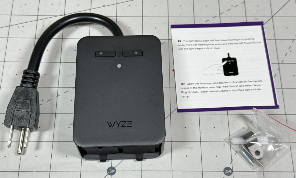
Example Solder-n-Flash: Wyze Outdoor Plug

Caption: Triangle-bit screwdriver and suction cup are helpful to remove cover / Image Credit: Jeremy Cook
While any ESP32-based device should be able to accept alternative firmware, some devices are easier than others to program. Per a bit of advice, I decided to take on the Wyze Outdoor Plug as a medium-difficulty flashing target. With the switch unplugged, disassemble it using a triangle driver and optionally a suction cup as shown above to reveal its insides. Do not plug it into mains until it is reprogrammed and reassembled.
While it doesn’t have the same unobstructed through-hole connections as Sonoff Basic devices or a built-in USB connection like the Wemos D1 Mini, it does have four of the five required pads in an unobstructed surface-mount format. Annoyingly, the fifth pad is under the mains cable, making things harder, but still relatively straightforward.
.jpeg)
Image Credit: Jeremy Cook
My technique here was to tackle the “easy-four” connections using a row of soldered-on headers. For pad #5, I very carefully soldered on a length of stranded wire attached to a female header. The challenge here is ensuring that you don’t touch and melt part of the internal mains wiring, which I (mostly) did not.
.jpg)
Image Credit: Jeremy Cook
After first attempting to use apparently inferior flashing devices, I purchased a CH340 module (plus four spares) and modified it with another row of headers. This allowed me to properly select the 3V3 transmission voltage (by jumpering 3V3 to VCC on the board), while also supplying 3.3V to the ESP32. This also allowed for a standard GND connection as well as GND to the boot select as needed.
However, your programmer is configured, ensure you’re using 3V3 to supply and program the ESP32. It is not 5V tolerant. Again, don’t plug it into mains yet!
Firmware Installation
Connect the CH340 board to your computer via USB, then connect the CH340 GND to the Wyze boot pin to enable programming. Connect 3V3, GND, and Rx (to Tx), Tx (to Rx). Download the tasmota32.factory.bin file from the Tasmota32 releases page, and use the web installer to upload the new firmware.
Once this is done, pull the 3V3 jumper, as well as the boot ground jumper, then replace the 3V3 jumper to allow it to boot in normal mode. If all is functioning correctly, you’ll be able to find and connect to a new Tasmota network, where you can input your WiFi credentials. With this info the Wyze switch will attempt to connect to your local network. You can then find it with an IP address scanner, navigate to it on your browser, and further configure your device.
From here, re-attach the cover plate and screws, plug it into mains, and you can manipulate relays and monitor your power usage. Note that the first device I flashed didn’t generate a WiFi network until I connected it to mains. That may have been a coincidence, and not an actual solution, but it may be worth trying (with attached cover) if you have problems. You also may choose to clip and remove the connector wire to avert potential future issues if it were to somehow become disconnected.
.jpg)
Image Credit: Jeremy Cook
Simple, is what I say now that I’ve done it twice and worked out the bugs after many hours of trial and error. Hopefully this guide will make things actually simple for you.
Custom Firmware for All Your Devices!
While the Wyze Outdoor Plug is an ideal(ish) device for modification, you can take what’s outlined here and apply it in a wide range of scenarios. Consider the aforementioned Sonoff devices and ESP-based smart light bulbs. Such devices should be flashable, but some will require more advanced disassembly/soldering techniques.
While the details will be different (e.g. ESP8266 vs ESP32 firmware), the general concept of new firmware for your purchased device is something to keep in your repertoire or tools for now, or when it may come in handy in the future. For further firmware setup info, many of the techniques outlined in the latter part of this Tasmota garage door article will apply here as well.
For more information on flashing this particular device, I found this John’s Tech Blog article extremely helpful, as was this digiblurDIY piece. Check it out for a different take on how to get the Wyze plug working with Tasmota.