A No-Code ESP8266 Night Light with Unicontrol and Touch Sensor
June 14, 2023
Blog
As a maker in expectation, I was given a direct task: to upgrade the old salt lamp we had been using as a baby night light. The upgrade was to include an optional 15-minute timer and introduce smoother fading transitions compared to the original 230V bulb.
I enjoy working with capacitive touch sensors and LEDs, which are making the task straightforward to execute. Even though an Arduino could accomplish this (given that no Wi-Fi connection is required by default), I have my favorite ESP8266 with ayatec unicontrol firmware at hand to complete the project without writing a single line of code.
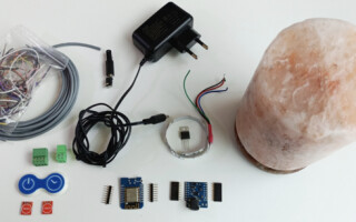
Budget
|
Item |
Price (€) |
|
ayatec unicontrol mini |
4 |
|
A short piece of a LED strip |
1 - 2 |
|
IRLZ24N MOSFET or similar |
< 0.5 |
|
2x Capacitive touch sensor TTP223 / HW-763 or similar |
< 0.5 |
|
Various cables and connectors |
2 - 3 |
|
12V 2A power adapter |
4 - 6 |
|
WeMos D1 mini ESP8266 |
2 - 4 |
|
WeMos DC Power Shield |
1 - 3 |

Depending on the parts chosen, you can expect the cost of this setup to range from €15 to €23, not including the original lamp and the printed case.
Assembly
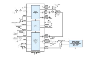
Hardware assembly is basic. I need two logical inputs from the capacitive touch sensors and a single PWM output for the 12V LED strip via an IRLZ24N MOSFET:

Tip: The IRLZ24N is my favorite, but in essence, it should be replaceable in this scheme with any N-type MOSFET that has a voltage rating (V(BR)DSS) of at least 12V, a current rating (ID) of at least 2A, and a maximum gate threshold voltage VGS(th) below 3V.
1. The critical part of the assembly is the user interface, or more simply, the touch buttons. You may use the 3D printed casing I modelled specifically for this purpose.


a. You can easily amplify their sensitivity by placing a small piece of metallic foil (copper or aluminium) over the intended contact area (in the direction of touch). Size and shape significantly impact sensitivity, so a bit of trial and error may be necessary to achieve the desired effect without triggering false positives. These sensors often have designated solder pads that can be used to connect to this auxiliary surface.
b. You can dampen the sensitivity by increasing the touch distance or introducing an insulating layer (any electrical tape). Cases made from common printing filaments (PLA, PETG, ABS) also function as insulators. A great help in filtering ambient EM noise can be the introduction of a metallic shield around (but not covering) the touch surface, and connecting it to the ground.
c. Avoid the presence of water (including droplets) as it can easily trigger the sensor. Also, be careful with wood, which is affected by the electric field. |


2. The DC Power Shield has a connector that prevents the desired assembly. Luckily, newer shields come with surface mounting for this connector, which can pop off when pulled with pliers with a bit of force.

3. The rest should be a straightforward assembly. I usually include a lot of connectors wherever possible for convenient installation and maintenance.


Program
- Download unicontrol and flash it onto your ESP8266
- Connect to your wireless network and navigate to the user interface. If you are new to unicontrol, you can follow this tutorial.
- In the Peripheral menu, you need to set:
- D1 as OUT - General (this will be the LED output)
- D4 as IN - Logical (this prevents the ESP8266 on-board LED from blinking, which would be inconvenient in this application)
- D5 and D7 as IN - Logical (these will serve as touch buttons)
- Click the “Save” button when you're done.

4. In the Processes menu, select the first process, name it as you wish (e.g., ON_OFF), and change the following:
- Main state: Auto (to enable evaluation)
- Input source: D5 (touch button 1)
- Primary output: D1 (LED strip)
- Type: PWM (to enable fading)
- On event + Off event: Rising edge (to switch on and off on button press)
- Fade-in + Fade-out: 2 seconds (the fader transition when switching on and off will take 2 seconds)
- Secondary output 1: 2: Process_2 / Off->Off (explanation later)
Click “Save”If you have correctly followed the instructions up to now, the LED strip should now be controlled by the touch button connected to the D5 pin. When you touch the button, the strip will slowly fade in and will stay on until it's touched again, when it softly fades out. The “On” and “Off” buttons in the same menu should work just the same as well.
5. Still in the Processes menu, select the second process, name it as you wish (e.g., TIMER), and change the following:
- Main state: Auto (to enable evaluation)
- Input source: D7 (touch button 2)
- Primary output: D1 (LED strip)
- Type: PWM (to enable fading)
- On event: Rising edge (to switch on upon button press)
- Off event: Timeout (to switch off automatically after some time)
- Running time: 3 seconds (for now, in the final application I will change this to 15 minutes)
Now, instead of defining the primary output for the second process, which would cause the two processes to behave independently, I would rather have them cooperate. This will ensure that the two buttons will transition fluently regardless of how quickly or in what order they are pressed. To achieve this, I will set the second process to control the first one instead of its own output, thus:
8. Secondary output 1: 1: ON_OFF / Same
Using this setting will turn Process 1 and its Primary output “On” and “Off” together with Process 2. For a similar reason, I have set Process 2 as the Secondary output for Process 1. However, this time, I only made it to turn “Off” as Process 1 turns “Off”, only to prevent the situation where Process 1 is turned “Off” while Process 2 and its running Timeout remains “On”.


-
The only remaining part is now to set the timers to their final values and install the lamp in its designated place.
-
Once the device is set up and activated, you may considered scrambling its Wi-Fi credentials as this application does not require an internet connection.
|
Please note that it's good practice to activate unicontrol only after the installation has been successful and properly tested. The 14-day free trial period is sufficient for this. |
Post installation
After the final installation, I found that the sensors were randomly triggered from time to time due to the EM noise in the designated place. This issue was resolved by increasing the Control period to two-tenths of a second in the Processes menu.
Further Improvements
The capabilities of the ESP8266 with unicontrol firmware far exceed what was showcased above. You can easily:
- Use the real-time Timers to switch the light on or off at specific times on specific days.
- Use the Duty cycle setting to control the brightness.
- Introduce additional sound or vibration sensors and switch on the light automatically upon disturbance
- Control the light remotely via the integrated MQTT or HTTP API
- Publish additional sensors’ telemetry via the integrated MQTT API
- And much more!