The Buffer/Driver: What Is It, and Do I Need One?
January 14, 2020
Story
Although buffers and drivers don?t appear to add functionality to a circuit, these apparently simple interface elements are essential to viable circuit design and operation.
The answers to that double question are simple: first, “it depends” and second, “almost certainly.”
Let’s start with definitions: “buffer” has many definitions in electronics hardware and software. It can be a reserved software area; a set of internal IC registers; or it can be a circuit function interposed to interface between two subcircuits.
We will look at the latter role. Although these buffers often handle digital signals consisting of idealized 1s and 0s, they are actually functioning in the real, analog world of voltage, current, time, and failures. As such, they are analog circuits handling real-world “digital” signals.
The difference between a buffer and a driver is largely a matter of perspective. A buffer is usually an interposed element which keeps the signal source from being affected by the load attributes but delivers the same or nearly the same voltage and current it sees at its own input. A driver, in contrast, often boosts the current source/sink level, or the voltage at which it delivers its output to its load, and often provide additional protection against circuit problems. However, the two functions often overlap and so does their naming in common use.
The buffer/driver symbol is simple, Figure 1, and does not begin to hint at their subtleties or internal complexities. In many ICs, the function is built into the source IC, but there are also many discrete buffer and driver ICs in use, depending how much current has to be delivered and at what voltage levels. (Note that buffers for analog signals usually use the same symbol as those for digital signals.)

Fig 1: The schematic symbol commonly used for a buffer/driver of analog or digital signals shows that it provides little or no additional functionality; instead, it takes the signal at its input, enhances some of its voltage/current attributes, and presents it as an output. (source: Atari Archives)
A buffer or driver can serve many distinct functions, even though a basic buffer or driver has a single input which is connected to a source’s output, and a single output which is connected to (or drives) the load’s input. Among the many buffer or driver roles:
- A buffer can translate the voltage of the source to the voltage needed by the load;
- It can allow a subcircuit with only low or modest current-source/sink capability to drive a load which requires more current to operate.
- It can provide protection for the source, in case the load has a fault, such as a short circuit or inadvertent connection to the power rail.
- It can control and manage the timing between the source signal and the voltage/current as seen by the load (slew-rate control).
- It can insulate the source from any changes in the nature of the load, so the source sees a fixed, unchanging load impedance.
- It can simply invert the input signal to properly match the two subcircuits.
- It can provide impedance matching between components, a critical requirement in RF circuits for achieving maximum power transfer and minimum loss.
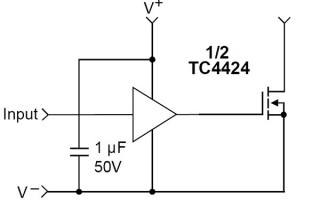
- A MOSFET/IGBT driver takes the low-level digital signals from a processor or controller and delivers them with the high voltage and current which the MOSFET needs to be turned on, with the carefully managed slew rate and timing, Figure 2.

Fig 2: This MOSFET driver takes a low-level digital output and translates it to the voltage and current needed to fully and quickly turn the MOSFET on and off. (Image source: Microchip Technology)
- A programmable logic controller (PLC) state-machine processor needs to turn a relay on and off, and the relay needs 24 V and 1 A to operate and also generates a high-voltage inductive “kick” when it is turned off; the driver not only translates between the two worlds but also protects the processor output.
- An IC with a 3-V output needs to interface to an IC with a 5-V input (or vice versa) although the current levels are low; a buffer acts as the voltage translator.
- An IC needs to drive multiple loads simultaneously, yet without interaction between these loads; a single-input, multiple-output buffer (multiple fan-out) does this, Figure 3.

Fig 3: A fanout buffer takes a single input and provide multiple outputs; the load or status on each output does not affect the others. (Image source: IDT/Renasas)
Again, these are just a few of many possible examples.
Sometimes, a buffer or driver provides more than just a basic electrical function. There are situations were two subcircuits must be electrically isolated from each other, meaning there is no ohmic (galvanic) path between the two, yet signal information must go from one to the other. This isolation may be needed for system protection, operator safety, or because the MOSFETs in a standard motor-driver need to “float” without ground connection. An isolated buffer breaks the galvanic path by using an interposed path using an optocoupler (optoisolator), a transformer’s magnetic path, a capacitive coupling, or even an RF link.
Despite the fact that buffers and drivers provide little or no added functionality or signal processing aspects, but primarily replicate their input at their output but with different attributes, they are essential components with key roles in a successful, viable design. Deciding which specific device to select is sometimes a simple decision, but it can be a complicated one when there are subtle tradeoffs that must be addressed, for example, when driving an SiC MOSFET or RF front end. The selection can “make or break” the reliable and successful performance of the circuit.
Related Content
Maximize the Performance of Your Sigma-Delta ADC Driver
Bioelectrical Impedance Analysis in Monitoring of the Clinical Status and Diagnosis of Diseases
Composite Amplifiers: High Output Drive Capability with Precision