High Fidelity Vibration Acquisition for Condition Monitoring
August 19, 2021
Blog
This article explains how recent advancements in MEMS technology have pushed accelerometer sensors to the forefront, rivaling piezoelectric sensors in condition-based monitoring applications. We will also discuss how to use the new development platform that makes this all possible.
In Part 2, we will focus on the software framework that supports this development platform, and how it can be integrated with popular data analysis tools to develop machine learning examples and, ultimately, how it can be deployed on various assets.
Introduction to Condition-Based Monitoring (CbM) and Predictive Maintenance (PdM)
Condition-based monitoring (CbM) involves monitoring machines or assets using sensors to measure the current state of health. Predictive maintenance (PdM) involves a combination of techniques such as CbM, machine learning, and analytics to predict upcoming asset maintenance cycles or failures. With significant growth projected in machine health monitoring globally, it is imperative to know and understand the key trends. More and more CbM companies are turning to PdM to differentiate their product offerings. Maintenance and facilities managers now have new options when it comes to CbM, such as wireless installations and lower cost, high performance installations. While most CbM system infrastructure remains unchanged, new MEMS technology can now be directly integrated into systems traditionally dominated by piezoelectric sensors or those not previously monitored due to cost barriers.
Condition Monitoring—Engineering Challenges and Design Decisions
In a typical CbM signal chain design, there are many different engineering disciplines required and technologies to consider, which are constantly improving and increasing in complexity. Various customer types now exist with expertise in specific areas such as algorithm development (software only) or hardware design (hardware only) but not always both.
Developers looking to focus on their algorithm development require data lakes of information to accurately predict asset failures and downtime. They don’t want to design hardware or troubleshoot the integrity of the data; they just want to use data that is known to be high fidelity. Similarly, hardware engineers looking to increase system reliability or reduce cost need a solution that can easily connect into existing infrastructure, to benchmark against existing solutions. They need access to the data in readable format that is easy to use and export, so they don’t waste time evaluating performance.
Many of the system-level challenges can be solved with a platform approach—from the sensor all the way to algorithmic development—enabling all customer types.
What Is CN0549 and How Can It Help Extend Equipment Lifetime?
CN0549 CbM Development Platform
The CN0549 condition-based monitoring platform is a high performance, off-the-shelf hardware and software solution that will allow high fidelity streaming of vibration data from an asset into the algorithm/machine learning development environment. The platform benefits hardware experts as it is a tested and verified system solution providing high precision data acquisition, proven mechanical coupling to the asset, and a high performance wideband vibration sensor. All hardware design files are provided, allowing for easy integration into the product you design. CN0549 is also attractive to SW experts, as it abstracts the challenges of the condition monitoring signal chain hardware and allows for software teams and data scientists to jump right into developing machine learning algorithms. Key features and benefits include:
- Easy mounting to assets while maintaining mechanical coupling signal integrity
- Wide bandwidth MEMS accelerometer sensor with IEPE data output format
- IEPE, high fidelity data acquisition (DAQ) solution with analog input bandwidth from DC to 54 kHz
- Embedded gateway captures and stores the raw data for local or networked processing
- Visualize frequency domain data in real time using ADI’s IIO Oscilloscope application
- Stream sensor data directly into popular data analysis tools such as Python and MATLAB®
The CbM development platform consists of four different elements shown in Figure 1, which we will discuss individually before looking at the combined overall solution.

Figure 1. Elements of the CbM development platform.
High Precision, High Fidelity Data Capture and Processing
Wider bandwidth and lower noise sensors enable earlier detection of faults such as bearing issues, cavitation, and gear meshing. It is imperative that any data acquisition electronics maintain the fidelity of the measured vibration data; otherwise critical fault information may be lost. Maintaining the fidelity of vibration data makes it possible to see trends sooner, and, with a high degree of confidence, we can recommend preventative maintenance, thus reducing unnecessary wear and tear on mechanical elements, and inevitably extending the lifetime of assets.
Cost-Effective Methods for Condition Monitoring on Lower Criticality Assets
Piezo accelerometers are the highest performance vibration sensor used on the most critical assets where performance requirements outweigh cost. CbM of lower criticality assets has traditionally been prohibited by the high cost of piezo installations. MEMS vibration sensors, now comparable to piezo in noise, bandwidth, and g-range, are enabling deeper insights for maintenance and facilities managers on lower criticality assets that previously have been covered by a run-to-failure or reactive maintenance schedule. This is primarily due to MEMS’ high performance and low cost. Medium to low criticality assets can now be continuously monitored in a cost-effective manner. Unnecessary wear and tear on assets can be easily identified and remedied, helping to extend the lifetime of assets through advanced vibration sensing. This can also contribute to overall equipment effectiveness and reduction of machine or process downtime.
Monitoring Assets—Sensing Matters
There are many different types of sensing modalities when it comes to CbM and PdM. Current sensing, magnetic sensing, flow monitoring, and several others make up most of the applications. Vibration sensing is the most common modality used in CbM, and piezo accelerometers are the most used vibration sensor. In this section, we will review how the vibration sensor landscape is expanding due to advancements in technology, and how that impacts the application decision making.
MEMS vs. Piezoelectric
Piezo accelerometers are very high performing sensors, but all that performance requires many design trade-offs. For instance, piezo accelerometers are typically limited to use in wired installations because they can consume excess power, they can be physically large (especially triaxial sensors), and they are expensive. When all these factors are combined, it’s not practical to outfit your entire factory with piezo sensors, which is why they are predominantly used only on critical assets.
Until recently, MEMS accelerometers did not have wide enough bandwidths, their noise was too high, and g-ranges were limited for use in monitoring less critical assets. Recent advancements in MEMS technologies have overcome these limitations, enabling MEMS vibration monitoring of both low end and even high criticality assets. Table 1 shows the most important characteristics required of piezo and MEMS sensors for CbM applications. Being physically small, capable of running for years on batteries, and being low cost with comparable performance to piezo, MEMS accelerometers are fast becoming the sensor of choice for many CbM applications.
The CN0549 CbM development platform is compatible with MEMS and IEPE piezo accelerometers, to enable a path for benchmark comparison between the sensor types.
Table 1. MEMS vs. Piezoelectric Accelerometers
|
|
Piezoelectric |
MEMS |
|
||
|
DC Response |
|
✓ |
|||
|
Shock Tolerance |
|
✓ |
|||
|
Integration Opportunities (3-Axis, ADC, Alarms, FFT) |
|
✓ |
|||
|
Performance Variation over Time and Temperature |
|
✓ |
|||
|
Power Consumption |
|
✓ |
|||
|
Physical Size (Smaller Is better) |
|
✓ |
|||
|
Self-Test |
|
✓ |
|||
|
Cost for Similar Performance |
|
✓ |
|||
|
Noise |
✓ |
|
|||
|
Bandwidth |
✓ |
✓ |
|||
|
Mechanical Attach |
✓ |
✓ |
|||
|
Industry-Standard Interface |
✓ |
✓ |
|||
|
g-Range |
✓ |
✓ |
|||
Using MEMS Accelerometers with Existing IEPE Infrastructure
As outlined in Table 1, MEMS accelerometers can now provide competitive specifications and performance when compared with piezo sensors, but can they replace an existing piezo sensor? For designers to easily evaluate and replace piezo accelerometers with MEMS accelerometers, Analog Devices designed an interface that is compatible with IEPE, the de facto standard piezo sensor interface in CbM applications.
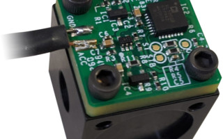
IEPE Sensor Interfacing and Mechanical Mounting (CN0532)
The CN0532, shown in Figure 2, is an IEPE conversion circuit that allows a MEMS accelerometer to interface directly to IEPE infrastructure as seamlessly as any existing IEPE sensor.

Figure 2. CN0532 MEMS IEPE conversion circuit.
Typically, a single-axis MEMS sensor would have three output lines: power, ground, and acceleration out. IEPE infrastructure only requires two: ground on one line and power/signal on the other line. Current is delivered to the sensor, and when the sensor measures vibrations a voltage is output on the same line.

Figure 3. A simplified schematic showing how a MEMS sensor can be interfaced to existing IEPE infrastructure (power and data).
The CN0532 PCB was designed with a thickness of 90 mils to maintain the data sheet frequency response performance of the MEMS accelerometer. A stud mountable cube allows immediate testing out of the box. The mounting cube, along with PCB, solder paste, etc., have been extensively characterized to ensure a full bandwidth mechanical transfer function, maximizing visibility of a wide range of faults within the sensor bandwidth, and thus extending asset lifetime by having the ability to capture these faults. These solutions make it very easy for CbM designers to attach MEMS accelerometers to their assets as well as seamlessly interfacing with existing piezo infrastructure.
For any high frequency vibration tests, mechanical signal path integrity is very important. In other words, from the source to the sensor, there must be no attenuation (due to damping) nor amplification (due to resonance) of the vibration signal. In Figure 4 an aluminium mounting block (EVAL-XLMOUNT1), four screw mounts, and a thick PCB guarantees a flat mechanical response for the frequency range of interest. The IEPE reference design makes it very easy for designers to implement a MEMS sensor in place of a piezo sensor.

Figure 4. Vibration measurement test setup: the EVAL-CN0532-EBZ board attached to a shaker table using an EVAL-XLMOUNT1 aluminium mounting block.

Figure 5. Frequency response of the EVAL-CN0532 compared to the ADXL1002 data sheet frequency response.
Vibration to Bits—Data Conversion Integrity
We now know that MEMS sensors can be used in place of IEPE piezo sensors. We have also seen how they can be easily mounted to assets while maintaining their data sheet performance. An important part of a CbM development platform is being able to gather high quality vibration data, whether it be MEMS based or piezo based, into the correct environment. Next, we will look at acquiring IEPE sensor data and maintaining the highest fidelity data to develop the best CbM algorithms or machine learning algorithms possible. This is enabled by another of our CbM reference designs, the CN0540.
High Fidelity, 24-Bit, Data Acquisition System for IEPE Sensors (CN0540)
In Figure 6 we see a lab tested and verified IEPE DAQ signal chain. This reference design provides the optimal analog signal chain for use with both MEMS and piezo accelerometers. Analog Devices does not just focus on MEMS accelerometer-based solutions. It is important to remember piezo accelerometers offer the highest performance and are the most widely used vibration sensor; therefore, piezo accelerometers are a focus sensor for precision signal chain offerings.
The circuit shown in Figure 6 is a sensor-to-bits (data acquisition) signal chain for an IEPE sensor consisting of a current source, input protection, level shifting and attenuation stage, a third-order antialiasing filter, an analog-to digital converter (ADC) driver, and a fully differential ∑-Δ ADC. CbM system designers using piezo accelerometers require a high performance analog signal chain to maintain the fidelity of the vibration data. Designers can evaluate the signal chain performance out of the box simply by attaching their IEPE sensor or the CN0532 IEPE sensor directly to the CN0540 DAQ reference design. Analog Devices has extensively tested this design and provides open-source design files (schematic, layout files, bill of material, etc.) allowing for easier design into end solutions.
The CN0540 IEPE data acquisition board is a tested and verified analog signal chain designed to acquire IEPE sensor vibration data, with better than 100 dB signal-to-noise ratio (SNR). Most solutions that interface with piezoelectric sensors in the market are AC-coupled, lacking DC and sub-Hertz measurement capabilities. CN0540 is suitable for DC-coupled application scenarios, where the DC component of the signal must be preserved or where the response of the system must be maintained down to frequencies of 1 Hz or lower.
The precision data acquisition reference design was tested with two MEMS sensors and three piezo sensors, as shown in Table 2. We can see the g-range, noise density, and bandwidth of each sensor is quite different, as is the price. It should be noted that piezo sensors still have the best noise performance and bandwidths for vibration.
In the case of CN0540, the system bandwidth is set to 54 kHz, and the signal chain noise performance is aimed at sensors that can achieve >100 dB dynamic range over that bandwidth—for example, Piezotronics PCB Model 621B40 accelerometer, which achieves 105 dB at 30 kHz. CN0540 was designed to have extra bandwidth and precision capabilities beyond current vibration sensor performance to ensure it will not be a bottleneck to collecting high performance vibration data. It is very easy to compare and benchmark MEMS vs. piezoelectric on the same system. Whether working with MEMS, piezo, or both, the CN0540 provides the best signal chain solution for data acquisition and processing, which inevitably can be designed into an embedded solution.
When we say that MEMS offer comparable performance at a much lower cost, we can see 83 dB SNR for the ADXL1002 but over 10 times lower cost compared to piezo sensors. MEMS have now established themselves as a viable alternative to all but the highest performance piezo sensors at a fraction of the cost.

Figure 6. CN0540: high performance, wide bandwidth, precision data acquisition for IEPE sensors.
Table 2. MEMS and Piezoelectric Sensors with Corresponding Noise Density Measurements
|
Sensor |
Range |
Output Range |
Linearity (%FSR) |
NSD (µg/√Hz) |
Flat Bandwidth (kHz) |
Noise at Flat Bandwidth (µg RMS) |
Dynamic Range at Flat Bandwidth (dB) |
|
ADXL1002 |
50 |
4 |
0.1 |
25 |
11 |
2622 |
82.60 |
|
ADXL1004 |
500 |
4 |
0.25 |
125 |
24 |
19365 |
85.32 |
|
PCB 621B40 |
500 |
10 |
1 |
10 |
30 |
1732 |
104.95 |
|
PCB 352C04 |
500 |
10 |
1 |
4 |
10 |
400 |
118.93 |
|
PCB 333B52 |
5 |
10 |
1 |
0.4 |
3 |
22 |
98.50 |
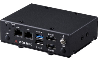
Embedded Gateway
Once the high fidelity vibration data has been acquired by the DAQ signal chain, it is important to process it and view in real time and/or transmit it to the machine learning or cloud environment—this is the job of the embedded gateway.
Process Vibration Data in Real Time Locally
Two embedded platforms are supported from Intel® (DE10-Nano) and Xilinx® (Cora Z7-07S), which include support provided for all associated HDL, device drivers, software packages, and applications. Each platform runs the embedded ADI Kuiper Linux®, which enables you to display time and frequency domain data in real time, provides access to the real-time captured data over Ethernet, interfaces with popular data analysis tools such MATLAB or Python, and even connects with various cloud computing instances like AWS and Azure. The embedded gateway can transfer 6.15 Mbps (256 kSPS × 24 bits) via Ethernet to your chosen algorithm development tool. Some of the key features of the embedded gateways include:
- Intel Terasic DE10-Nano
- Dual-core Arm® Cortex®-A9 MP Core processor at 800 MHz neon™ framework media-processing engine with double-precision floating point unit (FPU)
- 1 gigabit Ethernet PHY with RJ45 connector
- Digilent Cora Z7-07S (Xilinx)
- 667 MHz Cortex-A9 processor with tightly integrated Xilinx FPGA
- 512 MB DDR3 memory
- USB and Ethernet connectivity
IIO Oscilloscope, shown in Figure 7, is a free open-source application that is installed with ADI Kuiper Linux, helping you quickly visualize your time domain and frequency domain data. Built on top of the Linux IIO framework, it interfaces directly with the Analog Devices Linux device drivers, allowing for device configuration, reading device data, and visual displays all in one tool.

Figure 7. IIO Oscilloscope showing an FFT of a 5 kHz pure tone.
Industry-standard tools, such as MATLAB and Python, are also supported on the ADI Kuiper Linux Image. Using interfacing layers that work with the IIO framework, IIO bindings have been developed for streaming data directly into these typical data analysis tools. Designers can display and analyze data, develop algorithms, as well as perform hardware in the loop testing and other data manipulation techniques using these powerful tools in combination with the IIO integration frameworks. Full examples that enable you to stream high quality vibration data to either MATLAB or Python tools are available.
Predictive Maintenance Development Using the CN0549
There are five typical steps in developing machine learning (ML) algorithms for PdM applications, as shown in Figure 8. For predictive maintenance, regression models are typically used to predict upcoming failures over classification models. They perform better when they have more training data to input into the predictive model. Ten minutes of vibration data will likely not detect all the operating characteristics, whereas 10 hours has a much better chance of doing so—and collecting 10 days of data will guarantee a much stronger model.

Figure 8. Steps to develop a PdM application.

Figure 9. CN0549 example use case.
CN0549 provides the data collection step in one easy to use system where we can stream high performance vibration data to the ML environment of choice.
The MEMS IEPE sensor is provided with a mechanical mounting block, allowing seamless mounting of a MEMS sensor to an asset or shaker. Keep in mind IEPE piezo sensors can also be used with this system and attached to assets, shakers, etc. with ease. Before streaming data to the data analysis tools, the sensor attachment should be verified to ensure there are no unwanted resonances. This can very easily be checked in real time using the IIO Oscilloscope. Once the system is ready to go, a use case can be defined, as shown in Figure 9—for example, healthy operation of a motor at 70% load capability. High quality vibration data can then be streamed to MATLAB or Python-based data analysis tools such as TensorFlow or PyTorch (and many others).
Analysis can be carried out to identify key signatures and characteristics that define the healthiness of that asset. Once there is a model that defines healthy operation, faults can either be seeded or simulated. Step 4 is repeated to identify key signatures that define the fault, and a model is derived. Fault data can be compared to the healthy motor data, and prediction models can be developed.
This is a simplified overview of the ML process enabled by the CbM development platform. The key thing to remember is this platform ensures the highest quality vibration data is delivered to the ML environment.
Part 2 of this article will go into detail on software stack, dataflow, and development strategies, as well as cover some examples using both Python and MATLAB from the perspective of the data scientist or machine learning algorithm developer. An overview of the software integrations will be discussed as well as local and cloud-based development options.
Chris Murphy is an applications engineer with the European Centralized Applications Center, based in Dublin, Ireland. He has worked for Analog Devices since 2012, providing design support on motor control and industrial automation products. He holds a masterʼs of engineering in electronics by research and a bachelorʼs of engineering in computer engineering. He can be reached at [email protected].