Optimizing PoE Output Power Through Autoclass
January 29, 2019
Story

For those new to PoE, the technology allows power to be transferred alongside data over ethernet cables.
To match the demand for higher power in Power over Ethernet (PoE) applications like Wi-Fi Access Points and closed-circuit security cameras, the industry has released a new IEEE 802.3bt standard, which was ratified in September 2018. For those new to PoE, the technology allows power to be transferred alongside data over ethernet cables. The amount of power provided is managed by some handshaking that takes place between the Power Sourcing Equipment (PSE) and the Powered Device (PD) when they are connected. During this process, the PSE detects if the PD is PoE capable and, if it is, determines how much power is needed.
Power levels for PoE are defined by the device type and class. The latest standard adds two new types (3 and 4) and four new classes (5-8), which increases the possible output power the PSE can provide to 90 W. Key to permitting this increase in power is the ability to use all 4-pair conductors in an ethernet cable. Previously for Type 1 (15.4 W) and Type 2 (30 W) applications, only two pairs were needed to guarantee correct operation, but class 5-8 applications will require all four pairs.
While the IEEE 802.3bt standard states an output of 90 W for a PSE, it predicts only 71.3 W will reach the PD. This calculation assumes a maximum loss of 18.7 W across the ethernet cable predicted from the standard, which defines a "maximum pairset DC loop resistance" of 12.5 ? for 100 meters of cable. Previously, if the DC loop resistance in the system was lower than the maximum permitted by the standard the PSE would still reserve the maximum output power possible, even if the PD didn't need it. This meant any excess power in the PSE was left unused.
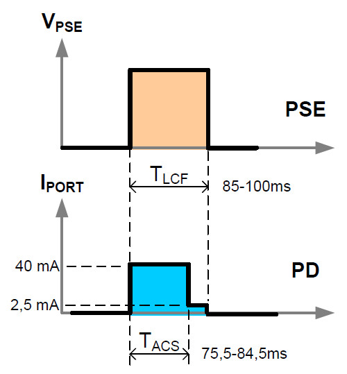
This is potentially wasteful so, to overcome this issue, the new IEEE 802.3bt standard introduced a feature called Autoclass, which optimizes power allocation. During the first-class event, the PD will indicate if it is Autoclass capable by adjusting the classification current from Class 4 (40 mA) to Class 0 (2.5 mA) after 81.5 ms (typ), as shown in the image below. The timing here is critical and can only be detected by an 802.3bt enabled PSE.
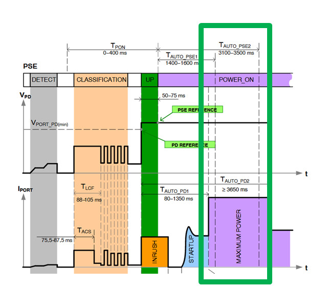
After system power-up the PD will draw the maximum power required for operation, which will be measured by the PSE. Using this measurement, the PSE can determine exactly how much power the PD actually needs and adjust its allocation level accordingly. This feature means the PSE can now optimize its total available power across multiple ports.
To better illustrate this optimization, the following PoE installation can be considered. If the average input power for a PD in this system is 42 W, the PSE port needs to allocate up to 51 W to account for the maximum cable length and budget a total power of 60 W based on the Class 6 assignment.
With autoclass enabled in combination with a short cable length (<1 W of cable loss), the PSE would only need to allocate 43.75 W. If eight of these PDs are powered by an 8-port switch, the switch would need to source 480 W of power without the autoclass feature. With autoclass and (<1W of cable loss per PD), the power budget of the switch could be reduced to 350 W resulting in a power optimization of 130 W for the system.
Using its unique high-voltage manufacturing process, ON Semiconductor has developed a new family of PoE solutions that are fully compliant with the IEEE 802.3bt specification. This process includes the lowest RDS (on) of any Hot-Swap FET in the market, which further increases the power efficiency of a PD application and lowers the overall PCB heat dissipation.
As these devices will support the new Autoclass request feature they will enable an 802.3bt-ready PSE to optimize its available power and support a greater number of higher power applications, enabling designers to more economically and efficiently measure the output power capability of the PSE in high power PoE systems.
Riley Beck is a member of the Industrial and Offline Products division based in Lindon, Utah, USA, where he manages a world-wide marketing team for the Energy Management Business unit. This business unit primarily focuses on circuit breakers, wired connectivity transceivers and Power over Ethernet devices.
Riley joined ON Semiconductor through the AMI Semiconductor acquisition and started his career as a mixed signal ASIC designer. His background also includes applications engineering for circuit breaker applications focusing on AFCI and GFCI technologies.
Riley Beck received his BSEE (2001) and MSEE (2004) in Electrical Engineering from Brigham Young University. In 2014 he completed the MBA Essentials program at the University of Utah David Eccles School of Business.