PC Fan Wiring for Customized Use
July 26, 2021
Story

When you purchase a PC fan for standard usage, it comes with a nice plug-in wiring harness that you simply connect to let it do its job... or so I assume.
While I’ve used PC-style fans in a wide range of applications, often extracted from old computers, I’ve never actually installed one the “correct” way.
If you examine these, you’ll notice they have between 2 and 4 wires. Two pins will be power and ground inputs, often red and black. A third wire in a 3-wire or 4-wire fan will give RPM feedback. The fourth wire is for PWM control, if it has one. How then do you connect these fans for non-standard usage?

The Quick and Dirty
As seen in the video, you can power a 12V fan with a 3V battery pack, or a 9V battery, though it will certainly be weak compared to a proper 12V supply. There the white wire is left unconnected, which is likely for RPM feedback. In the embedded video below, power for a 4-wire fan is connected to the red and black wires via a Raspberry Pi. The fan, however, does not switch on until its PWM control line is connected to 3.3 or 5V power, for a 100% duty cycle “PWM” signal.
In other cases, a fan will spin at 100% when the PWM line is not connected to anything. This matches up with Intel’s specs according to this Electro Schematics article, as well as other experiments that I’ve done when the PWM pin is floating. When connected to positive, the fan also spins, but when tied to ground it turns off. Standards here appear to be fairly loose, so some experimentation may be in order.
4-Wire PWM Control
PC fans generally take well under an amp of current to operate, but you’ll need to add a transistor for CPU/microcontroller control if using a 3-wire fan. For such applications, I’d humbly suggest using my EZ Fan2 PCB, which includes a flyback diode for long-lasting operation.
If you’re using a 4-wire fan with a PWM input, it is possible to control this type of fan with a computing device directly, such as Raspberry Pi’s GPIO pin, without an additional transistor. This type of operation is shown at around 2:22 in the above video.
In the case of the Pi, the fan is simply turned on and off, but it is possible to produce more granular speed control. According to the Electro Schematics article referenced earlier, a PWM input of 25kHz is the Intel standard for fan input, with an acceptable range of 21kHz to 28kHz. In my case, 20kHz was easy to generate, and using a square wave at that level, I was able to regulate a new Noctua 4-wire fan’s speed. I tried later with a different instrument pegged at 25kHz, which worked quite well as expected.
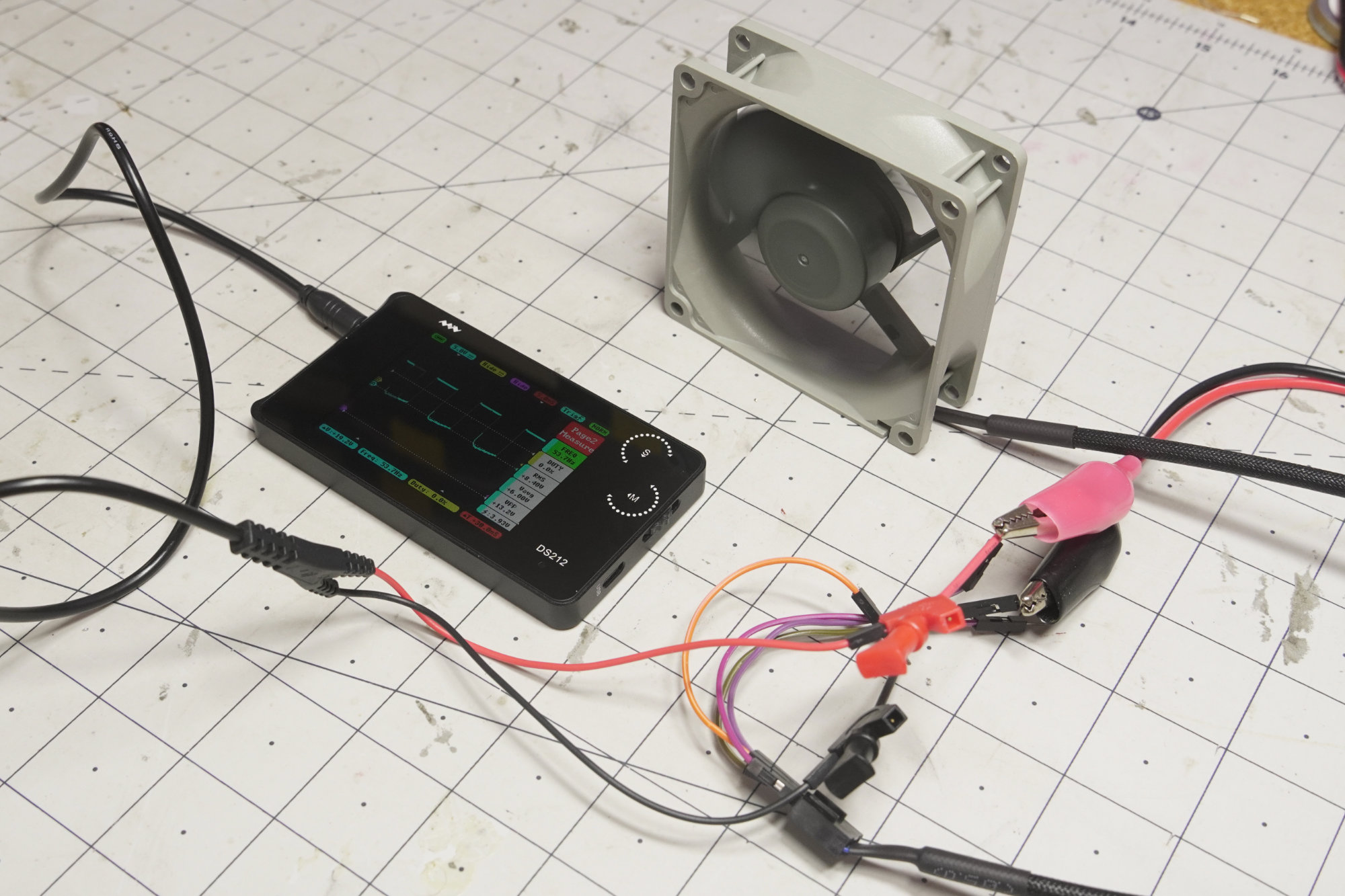
This particular fan is set up to spin at full speed with just the power and ground pins connected, consistent with the Intel standard. Colors are Black (ground), yellow (power), green (RPM feedback), and blue (PWM input). With the exception of black for ground, it seems you can’t necessarily rely on these colors being standardized. The wiring harness arrangement, however, appears to stay consistent (ground, +12V, RPM feedback, PWM input), so it’s best to check that out if you’re in doubt.
Third-Wire RPM Feedback
So, what about that RPM feedback? In theory this would allow for closed loop fan control, or potentially more critical, could give you a warning when cooling is offline.
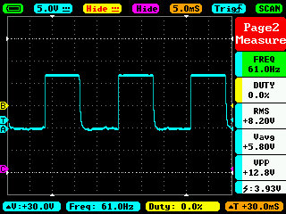
To see how the fan is performing, hook up the positive line of your scope to the positive fan input, and ground to the tach output pin. The signal outputs 2 pulses per revolution of the fan. With the fan at full speed (i.e. floating PWM pin) I read a varying 55 pulses per second, then a somewhat more consistent 61 RPM in a later experiment. These numbers work out to be 1650 and 1830 RPM respectively, which correspond nicely to the fan’s 1800 RPM rating.
Conclusion
Having experimented with a variety of PC cooling fans, it seems that the connectors stay consistent: GND, 12V input, tach, PWM arrangement. How the fans function varies somewhat, and the wire colors are not to be trusted. Still, they’re a great cost-effective resource when you need to move air around. It’s best if you can get a spec sheet, but failing that, a little experimentation may be in order!
Jeremy Cook is a freelance tech journalist and engineering consultant with over 10 years of factory automation experience. An avid maker and experimenter, you can follow him on Twitter, or see his electromechanical exploits on the Jeremy Cook YouTube Channel!