Battery Management Systems 101: Powertrain Electrification
January 18, 2019
Story

Tipping point for powertrain electrification ? (EVs), (HEVs), (PHEVs) ? is in sight with modern lithium-ion batteries able to store and use energy in vehicles at higher power density and lower cost.
The tipping point for powertrain electrification — electric vehicles (EVs), hybrid electric vehicles (HEVs) and plug-in hybrid vehicles (PHEVs) — is in sight with modern lithium-ion batteries able to store and use energy in vehicles at higher power density and lower cost. According to an internal study from automotive chipmaker NXP, 50 percent of vehicles sold across the globe will have some form of electric propulsion by 2030.
At the same time, however, lithium battery cells have significant challenges that demand a sophisticated electronic control system. Enter the battery management system (BMS).
According to media reports, the “range anxiety” has been the key reason why Volkswagen engineers underestimated the ambitious road to vehicle electrification for so long. The industry observers call it a costly mistake on Volkswagen’s part. Though the German carmaker claims it’s catching up on electric drive technology with a massive boost in R&D funding.
The BMS electronics is a crucial part of powertrain electrification because it monitors and manages the condition of lithium-ion battery cells to ensure a safe, reliable and optimum battery operation. The role of BMS becomes especially critical amid the harsh and unpredictable environments in automotive designs.
The article will take a closer look at the anatomy of BMS and will show how an efficient and accurate BMS solution addresses the range-related concerns by employing battery monitoring and equalization technologies.
Anatomy of BMS
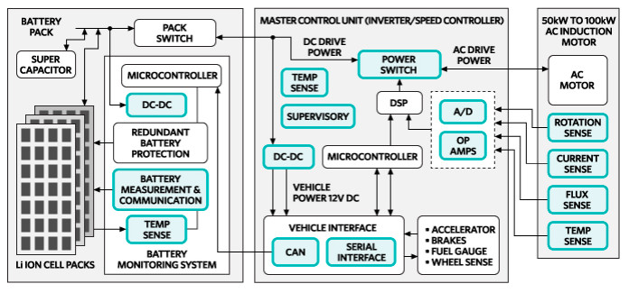
Let’s begin with the battery pack, an array of lithium-ion cells that must be carefully monitored and balanced. The battery cells — in hundreds or even thousands — constitute a battery that generates voltages up to hundreds of volts. The battery passes on the DC voltage to the inverter that employs AC traction motors to provide acceleration for electric vehicles.

Here, on the battery side, a BMS solution carries out three primary functions in vehicle electrification: battery cell monitoring, state of charge (SOC) estimation, and battery cell equalization.
Below is a sneak peek into these key building blocks of the BMS solutions that come in different battery pack and powertrain configurations.
1. Battery cell monitoring
The deployment of large batteries offering 400-V to 800-V systems inevitably demands accurate monitoring of cell voltage. Here, a BMS solution facilitates battery cell monitoring by providing information on current, voltage, temperature, etc. in real-time conditions. And that plays a vital role in facilitating the early failure detections in electric vehicle batteries.
A battery monitoring chip is usually a microcontroller monitoring the voltage of a cell or a group of cells. Furthermore, it typically performs temperature measurement of the battery pack and possibly of the cells themselves.
There are usually two major subsystems in the BMS electronics. The cell monitoring controller (CMC) reports voltage and temperature data to the battery monitoring controller (BMC), which passes on the data summary to an electronic control unit (ECU) via the CAN bus. There are distributed and centralized system designs when it comes to BMS architecture comprising the CMC and BMC components.
The fact that BMS accurately monitors battery cells by closely tracking the degradation of system performance also allows it to report the state of charge of battery packs. And that brings us to the next BMS building block.
2. State of charge
Lithium-ion batteries are vulnerable to damages caused by both over- and under-charging of the battery cell. And, state of charge or SOC, one of the most important parameters in BMS, represents the difference among individual battery cells.
The over-voltage or over-charging at excessive currents can cause thermal runaways. Moreover, not every cell in a battery pack loses charge at the same rate even though cells are connected in series. That’s because the charge cycle of a cell relies on several factors, including temperature and location of a cell in the battery.
The BMS electronics, which provide accurate predictions for vehicle range and battery life expectancy, implements predictive algorithms to estimate the battery cell performance accurately. Next, it ensures that a cell isn’t charged at 100 percent of its SOC or discharged at 0 percent of SOC, as both will degrade the battery capacity.
One way to maximize battery pack capacity and minimize degradation is by accurately controlling the SOC of each battery cell. As a result, the BMS electronics can ensure that the charge of battery cells remains within the recommended range. And that’s done via cell balancing.
3. Battery cell balancing
The difference between cell voltages, which indicates an unbalanced cell at the system level, can affect both individual cells and battery pack. One of the main causes of cell failure is cell voltage imbalance caused by leakage current in individual cells.
The BMS ensures that cell voltages don't exceed the rated maximum voltage, and it does that by employing passive and active balancing techniques. But a high-value resistor used in a passive balancing design itself dissipates power and it doesn't respond to the temperature variations common in automotive design environments.
The two major active balancing techniques are based on op-amps for voltage balancing and current balancing using the MOSFETs, respectively. However, op-amps can cause a swear power penalty if there is a mismatch between the capacitance values of two cells.
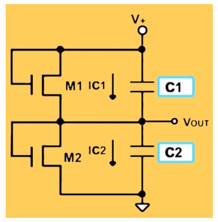
On the other hand, MOSFETs, which enable natural cell balancing through complementary opposing current levels, ensure that there is little or no additional leakage current from the MOSFET itself. The MOSFET is put in parallel to a battery cell or stack of cells connected in series.
The BMS value chain
The article has shown that if the state of charge of a battery pack is accurately monitored, there won’t be issues regarding battery cells. However, if a problem does arise relating to over-charging or under-charging of battery cells, auto-balancing of battery cells ensures the safe supply of voltage to the inverter in electric vehicles.
The BMS electronics will continue to evolve while more EVs and HEVs arrive on roads. But it has been able to fulfill the requirements of the present by efficiently monitoring and managing the cells in vehicle batteries.