
Thermal simulation optimizes cooling in high-performance systems
May 01, 2008
Story

New technologies like Computational Fluid Dynamics (CFD) software are making it possible for engineers to effectively deliver thermal management exper...
Thermal issues present some of the most critical challenges embedded designers face as they try to achieve maximum performance while keeping size, weight, and cost down. Applications in medical, industrial, telecommunications, and military environments have huge performance demands, thereby requiring faster processors. As operating frequencies increase and process geometries continue to shrink, high-performance processors are becoming the biggest culprit of heat generation, giving off as much as 120 W per processor. With power levels rising, designers need effective tools to validate thermal management early in the design process.
Importance of thermal design
The lifespan of a component as well as the entire system is directly tied to the heat it generates and the system’s internal temperature. Excessive temperatures can result in performance loss and, ultimately, component failures. For embedded systems that require high availability and longevity, this can be disastrous. Consequently, cooling has become an important design consideration. Where designers choose to place components, airflow vents, pressurization, and heat sinks has a measurable effect on thermal management.
To further complicate today’s embedded system designs, certain applications have additional requirements for sealed enclosure designs. For example, military equipment must be able to operate in extreme temperature fluctuations and high altitudes where air is thin and ineffective for cooling - all while undergoing extreme vibration and shock. This often calls for sealed designs that rarely or never exchange enclosure air with outside air, limiting which thermal management techniques designers can employ. These types of rugged designs are often encased with outside protection using high-density rubber that retains heat. Engineers must be mindful of application requirements when determining how to dissipate heat in these designs, particularly rugged handheld computers that cannot be too hot to handle in the field.
Thermal management techniques
Embedded system engineers have many options available for addressing heat issues. Heat sinks come in a vast assortment of types and sizes. Several special epoxies allow a heat sink to be glued to a component, providing increased surface area to dissipate heat away from the IC. Mechanically modifying the embedded system enclosure and mounting custom-designed heat sinks can remove heat from individual or multiple components. The back corners of the chassis can act as heat traps, allowing special baffles to deflect air to a particular location.
Internal component-mounted as well as enclosure-mounted fans can be incorporated to provide a constant airflow directly to the components and the internal system circuit board. When system design restrictions prohibit using fans or advanced cooling systems and require hermetically sealed enclosures, designers must often resort to more creative methods. Utilizing a different board with decreased features, reduced clock speeds or an alternate CPU, and more power-efficient storage is sometimes the only way to resolve thermal problems in these designs.
However, predicting and adjusting a system’s thermal footprint is only part science. Thermal management requires some guesswork or tribal knowledge based on an engineer’s previous experience. Yet there is no guarantee that the engineer will pick the right combination of values to investigate which one will lead down a time-consuming path of trial-and-error refinement techniques.
New technologies eliminate guesswork
To help improve the design’s overall reliability and avoid costly redesigns, thermal management must be validated early in the design process so that any problems can be addressed before the hardware is built. New technologies like Computational Fluid Dynamics (CFD) software are making it possible for engineers to effectively deliver thermal management expertise early in the design process long before physical prototyping and testing.
Prior to CFD software, an engineer would attack thermal issues through a cycle of exercises. Each approach required building a prototype, then taking the thermal measurements and making modifications until the desired thermal results were achieved. This often took months of building and testing before the correct design was identified, increasing time to market.
Today, simulation tools can enable engineers to create virtual models of electronic equipment, perform thermal analysis, and test design modifications quickly (often in less than 24 hours) and easily in the early stages of the design process. With a few mouse clicks, designers can rapidly develop “what-if” models, calculate the results, and compare performances.
Flomerics’ FLOTHERM software is an example of an application designed to address the challenges of modeling thermal management in electronic and electrical systems. The software enables users to predict airflow and heat transfer in and around electronic equipment, including the coupled effects of conduction, convection, and radiation.
Figure 1 illustrates the active heat-sink temperature plot of an ETXexpress module using this software. The stream in blue to red flowing through the heat-sink fins represents the airflow blowing from the fan on top. The right side shows the temperature reading starting at +50 °C from blue to red.
|
|

Thermal simulation can be helpful in designing an optimal chassis cooling system. The ability to create a model environment that predicts airflow, temperature, and heat transfer and validates the thermal design can cut design time significantly. An independent survey by the Aberdeen Group found that thermal analysis software users completed thermal design verification 3x faster and had more than 40 percent fewer re-spins on average per PCB design than nonusers.
Thermal analysis in action
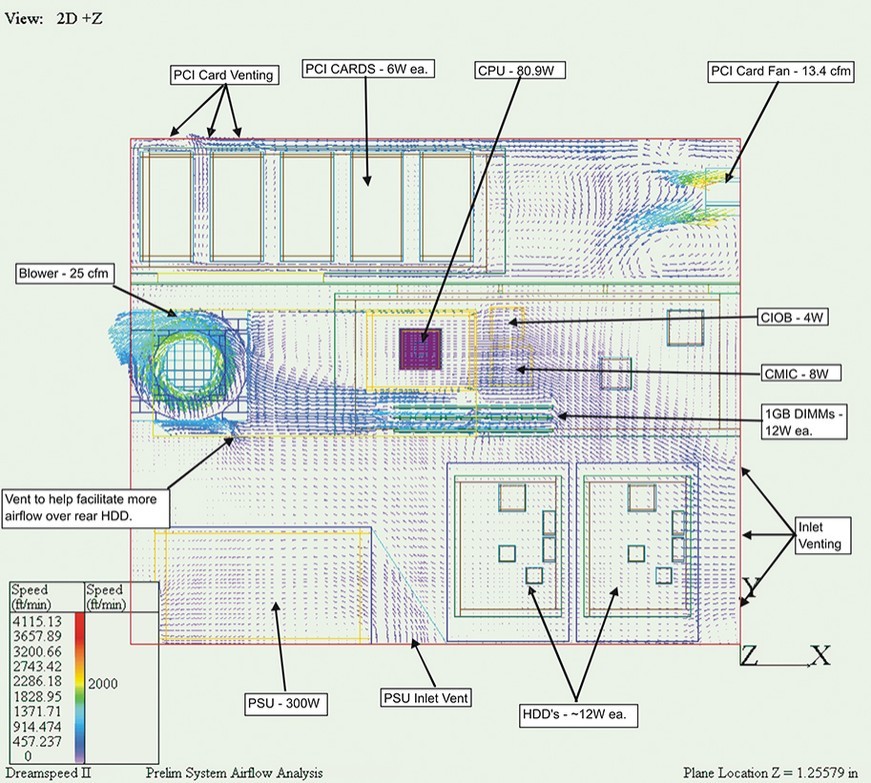
Figure 2 illustrates the preliminary system airflow analysis showing airflow direction, magnitude of speed, and fluid field strength on a 1U chassis temperature vector plot. Using this analysis, engineers can determine if individual commodities on the board need to be moved or replaced or if a particular component or its placement is causing a temperature anomaly.
|
|
Kontron used FLOTHERM in a network appliance wireless server design because of its ability to reliably simulate the final system’s performance and predict worst-case scenarios early in the design process. This particular system had several unknown variables and was based on proprietary cards that were available only as a specification at the time. To complicate matters, the spec had a wide range of power variables from 60-120 W.
Kontron’s engineering team took the specification and assigned different values to the CPU, HDD, memory, and I/O to generate a number of scenarios. Figure 3 shows an example of a small form factor monitor point graph that illustrates the temperature of different variables, such as the enclosure, CPU, and other components within the chassis. This simulation provided designers a view into the chassis to see thermal characteristics and anomalies and allowed them to predict worst-case scenarios, including what would happen in the event of a fan or other key component failure.
|
|

Once designers validated the model using simulation tools, they built a prototype and tested it in the customer’s real-world environment. Because analysis was completed early on and the results were virtually validated using simulation tools, the design held up to the customer’s needs.
Tools ensure reliability
Thermal requirements must be addressed at the beginning of the design cycle in today’s high-performance embedded systems. With the advent of CFD, engineers can virtually eliminate prototyping time and cost, software can pick the direction in which to move the parameters, and users can find the optimum design. Using this conceptual design process, thermal simulation can provide engineers with a key tool to reduce design time and the number of re-spins. Perhaps even more importantly, making good use of these tools enables designers to predict and plan for failures - reducing design risks and improving reliability for mission-critical applications.
Kevin Rhoades is VP of business development at Kontron America, where he is responsible for managing the North American Systems Division in Poway, California. Kevin has 25 years of experience in global supply chain and contract manufacturing and holds a BS in Business from Gonzaga University in Spokane, Washington.
Kontron America
888-294-4558
[email protected]
www.kontron.com


