
Test-Driven Development: Designing high quality from the start
July 01, 2008
Story

Experience shows that if a system isn't well designed and implemented, then testing cannot improve its quality ex post facto.
While all systems are tested before they go into production,
their quality is sometimes low. Experience shows that if a system isn't well
designed and implemented, then testing cannot improve its quality ex post
facto.
A Test-Driven Development (TDD) process improves quality
because it applies requirements-based testing throughout the development life
cycle, not just at the end of the project. With TDD, designs are built from
high-quality components known to be correct. This process maximizes system
quality because it reduces the number of defects before the artifact reaches
acceptance testing.
Testing phase by phase
Conventional methods divide the development process into
three basic steps: design, implement, and test. The problem with this approach
is that the two types of strategic defects, those related to requirements and
architecture, are often introduced early but detected late. Of all defects,
these two are the most costly because they can significantly affect most or all
of the system.
If tested primarily at the end of the development cycle, the
system is likely to include defects with complex design interdependencies,
making their identification and removal expensive, error-prone, and
time-consuming. These strategic defects are often not identified until the
validation phase when they might have thousands of subtle dependencies based on
assumptions that the fix invalidates. Finding these dependencies and repairing
them can be difficult.
TDD solves this problem by building and testing small system
components over time. With TDD, testing is not dealt with all at once toward
the end of the development cycle. Instead, it is performed incrementally
throughout the development life cycle to ensure that the system works as
specified at every phase.
This incremental approach requires that developers test a
project at every stage of its development, meaning that the system must be
constructed from executable and testable models. Scenarios specified during
requirements capture are used in downstream development to show that models are
correct and meet the requirements. The goal is to identify strategic defects as
early as possible; these defects can cost up to 1,000 times more than coding
defects if they are discovered late in the project. A good rule of thumb is
that no more than 5 percent of defects should be identified in the last 10
percent of the project life cycle.
UML plays an integral role in TDD
The Unified Modeling Language (UML), a standard technology
many engineers use to specify and structure their systems, makes TDD methods
possible. Many projects now use UML exclusively to represent and specify system
engineering characteristics and requirements. This enables a seamless handoff
to software engineering, which selects elements from the requirements set for
construction. Development builds the system incrementally, adding new
system-level capabilities to the increasingly complete and capable system.
Modeling real-time and embedded systems with UML provides two
primary benefits. First is the ability to specify, represent, and easily
understand different aspects of a system, including structure, behavior, and
Quality of Service (QoS). The second is the ability to represent these aspects
at different levels of abstraction, from high-level architecture all the way
down to highly detailed design. These benefits are unavailable if source code
is the only design representation.
UML provides moderate benefits for small systems ranging from
10K to 30K lines of code, and its value grows dramatically with system size.
For systems of 150K lines or more, effective UML adopters report up to an 80
percent improvement in time to market and an order of magnitude improvement in
quality, as measured by the defect rate.
TDD is realized as part of integrated product development
processes, such as the Harmony/Embedded Software process that defines product
development through requirements capture, systems engineering, the iterative
development design life cycle, and final test and validation. The process
includes a systems engineering workflow for requirements analysis and a systems
architecture that uses UML exclusively for representing and specifying systems
characteristics.
The UML Testing Profile
The Object Management Group (OMG), the consortium that
manages UML and other standards, has released the UML Testing Profile
(available at www.omg.org, see document formal/05-07-07). This specification
defines a language (a profile of UML) for "designing, visualizing,
specifying, analyzing, constructing, and documenting the artifacts of test
systems." It defines a test system's fundamental concepts and relations
using a reference metamodel on which the profile is based.
In addition, the profile defines a Test Architecture as
containing an Arbiter (determines whether a test passes), Scheduler (controls
different test components' execution), System Under Test (SUT), and so on.
Definitions regarding the test architecture, test context (grouping of test
cases), and the means by which test cases are specified (typically sequence or
activity diagrams) are of particular interest to embedded developers.
The profile is valuable because it provides a means for
understanding and specifying test environments, how to run tests, and how to
capture test cases. Because the profile defines standard methods for
accomplishing these tasks, testing elements can be interchanged between
different tools and organizations.
Tools compliant with this standard, such as Rhapsody Test
Conductor from Telelogic (an IBM Company), can automatically generate test
architecture elements and assist in reusing requirements artifacts as test
cases. Figure 1 shows a simple example of an automatically generated test
architecture. Test Conductor also can directly execute test context and its
included test cases as well as determine whether they pass or fail. This and
other examples demonstrate how the UML Testing Profile has enabled significant
improvements in constructing and executing tests for UML models.
|
|

Capturing and organizing requirements
UML organizes requirements by capturing the many small
details that specify what is meant by requests such as "analyze a blood
sample" or "process a customer transaction." The first step is
to capture the functional requirements that define what the system must do and
the QoS requirements that define how well it must perform.
Systems Modeling Language (SysML) requirements diagrams can
be used to create a taxonomy of the captured requirements. SysML, a derivative
profile of UML, enables requirements to be represented as model elements,
allowing requirements to become an integral part of the model architecture.
Requirements diagrams describe the requirements and their relationships to
other model elements. Besides requirements, these diagrams are used to
represent traceable links from the requirements to model elements such as use
cases, sequence diagrams, state machines, classes, and test vectors.
Once requirements are understood, they are clustered into use
cases and a set of scenarios, each depicting an interaction between a user and
a system, to describe the system's specific operational aspects. Use case
diagrams show capabilities and requirements in a black-box behavioral view that
does not attempt to explain how the system works. Figure 2 shows a use case
diagram overlaid with a description of the use case. A typical use case has up
to several dozen scenarios detailing the system's interaction with its
environment.
|
|

Use cases are typically created by listing a sequence of
steps (including branch points, concurrent activities, and resource sharing) a
user might take to use the system for a particular goal. The system must perform
actions derived from these steps. Visually describing a system's behavior
ensures that the development team and the customer understand the requirements'
intent.
State diagrams provide the behavioral specification view of a
single use case and specify how the system or its parts will react to events of
interest. State diagrams capture requirements with states, events, actions, and
collections of states linked via transitions. As events occur, these diagrams
define all possible system states and flows during use case execution. QoS
requirements are captured in state diagrams and sequence diagrams as
constraints and user-defined rules applied to one or more model elements.
Scenarios capture functional requirements as a set of
partially ordered messages sent between model elements at some level of
abstraction. As an essential part of development, scenarios are defined using
sequence diagrams that specify what the system or component must do.
Sequence diagrams define each use case's interaction flow and
capture the requirements in an inherently executable way, facilitating systems
testing. Sequence diagrams also define the behavior of elements in a use case
(for example, the system, use case, and actors) by the elements and messages
they send and receive. As illustrated in Figure 3, sequence diagrams are used
to show how multiple elements interact over time.
|
|

It is common to construct a state diagram for a use case and
then derive a set of scenarios from it, such that each looping and nonlooping
path is represented at least once. These scenarios can then be used to explore
requirements with nontechnical stakeholders and later be turned into test
vectors.
Developing subsystem specifications
During the analysis phase, black-box scenarios are elaborated
and requirements traceability is defined. The system model can be executed, and
its actual behavior can be compared with specified scenarios. Once system
requirements are defined, developers can begin constructing a system
architecture that supports the required capabilities. When different
technological or architectural systems must be evaluated, developers can
construct separate models to explore the systems' costs and benefits. Based on
this trade-off analysis, model artifacts collectively known as subsystem
specifications are developed, including
subsystem requirements, system and subsystem interfaces, and subsystem context
or system architectures for handoff to downstream engineering processes.
Following subsystem specification, each subsystem is decomposed
into its individual engineering disciplines during the transition phase between
systems and development engineering. Once this decomposition is completed,
subsystem-level, engineering-specific specification models can be created for
software, electronic, mechanical, and possibly chemical engineers. A schedule
also can be created detailing which artifacts from the different engineering
disciplines will be created at what time and how they will be integrated into
the evolving, incrementally constructed system.
Software engineering is the primary discipline relevant to
this discussion. The software portion of the subsystem model handed off is
represented as a UML model comprising software requirements, the architecture
into which the software must fit, and interfaces between the software and
electronics. Following the handoff, the iterative
analysis/design/implement/test cycle can begin as software engineers continue
to develop more detailed UML models to design their portion of the subsystems.
An incremental development cycle
Development proceeds interactively and incrementally through
analysis, design, and test phases. The subsystem software team begins with
requirements and context specification, selecting functionality organized
around software subsystem use cases.
In the analysis phase, development identifies and details the
use cases that should be added to the system build ("prototype"). A
domain analysis identifies the classes, objects, functions, and variables
essential to software, producing a Platform-Independent Model (PIM). As the
internal subsystem elements are defined, test fixtures and test cases are
defined simultaneously or immediately beforehand. The PIM itself is executed by
generating code for the model (either automatically or manually) as each new
element is introduced or modified. During this execution, unit-level tests are
reapplied to ensure that the PIM is working as expected. By the time the
analysis phase is complete, the PIM realizes all the functional requirements
for the selected use cases.
The project then enters the design phase, which optimizes the
system against the product's design criteria, including properties such as
worst-case performance, throughput, bandwidth, reliability, safety, security,
time to market, complexity, and maintainability, weighted in order of
importance. At the end of the design phase, an optimized Platform-Specific
Model (PSM) is the primary output artifact.
With a high-quality, integrated design environment, code
generation from the UML model is almost entirely automated. Some of the code
will occasionally be written by hand. Legacy code might be included in the
output by specifying the included code in the component configuration.
Precompiled components such as math libraries and protocol stacks might be
included in the link stream as well. In TDD, test cases and fixtures are
generated at the same time. The model is constantly re-executed and retested,
resulting in a high-quality PIM implementation.
Design proceeds by identifying design patterns that optimize
the most important design criteria at the expense of the least important
criteria; this means that the PIM is optimized by adopting technologies to
achieve design goals, resulting in the PSM. During the design phase, test cases
and test fixtures are updated and refined, and test cases are reapplied. In
this case, unit-level testing ensures that optimization during design didn't
break the PIM's already-working functionality and that optimization goals have
been achieved.
Four enabling technologies, including model execution,
collaborative debugging, requirements-based testing, and model-driven automatic
test generation enable repeatable and cost-effective testing throughout the
development process. This makes it practical to run tests continuously by
performing frequent regression testing whenever design coverage is increased
and reduces the cost of quality by creating relatively defect-free design
elements.
Formal requirements captured through sequence diagrams and
state charts plus requirements traceability to analysis, design, and test
vectors make it practical to automatically generate tests that cover all
aspects of the specification. Model-based execution eases visualization and
debugging by supporting debugging at the design level, similarly to how a
source code-level debugger allows the machine code execution to be visualized
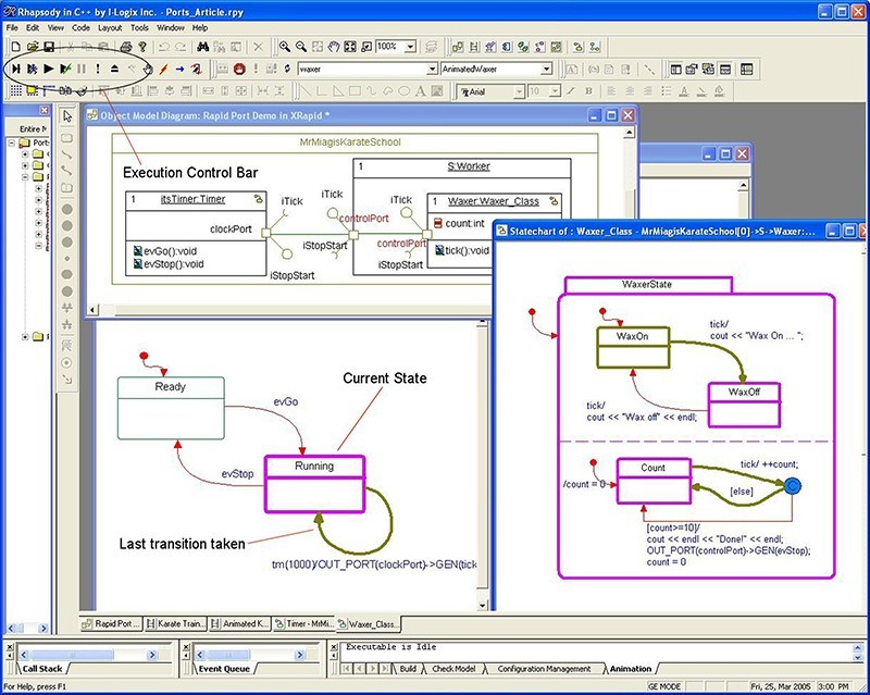
at the source code level. Figure 4 shows an example of a debugging session in
which state machines of different objects are shown as those objects respond to
incoming events.
|
|
Important considerations
In incremental development, testing is used to demonstrate
that the system is correct both in terms of functionality and QoS throughout
development, not just at the end. Strategic defects are identified as early as
possible to minimize the impact of removing them. In this way, the system is
constructed with high-quality design elements proven to work as early in the
life cycle as possible. Testing is performed on a continuous basis rather than
at the end of the project. Requirements-based testing ensures that the design
pieces always work to meet system needs.
Sequence diagrams play a critical role in TDD because they
represent requirements and can be easily converted into test vectors.
Scenario-based testing is typically used for conformance, regression, and unit
testing. This approach saves tremendous time and effort because it eliminates
manual test vector production and test execution.
Several different issues must be addressed before sequence
diagrams can be converted into test vectors. The first step is to distinguish
between what must exist or happen (causal) and what might exist or happen
(noncausal). Message event ordering is an important aspect of this analysis. In
some cases, several messages must occur prior to attaining some system
condition, but the order of those messages might not be important. This can be
accomplished by adding a constraint {unordered}
to that set of messages. Distributed systems also must include the notion of message
overtaking, in which message A sent prior
to message B actually arrived after message B. Thus, developers must consider
the send and receive events associated with each event and the relative event
ordering.
Sequence diagrams support the concept of partial ordering,
meaning that some orderings are specified while others are not. In general, all
message events on a given instance timeline in a sequence diagram are fully
ordered while other orderings are not specified, and messages are received only
after they are sent. Conclusions cannot be drawn about messages on different
instance timelines or in different instances regardless of their position in
the diagram unless they are related by one of these two rules. If it's
important to specify that some portion or even an entire sequence diagram is
fully ordered, this can be accomplished with a {strict ordering} constraint that applies to that
section or by using the UML 2 strict
interaction operator.
Another concern with using sequence diagrams for testing is
that they often don't provide a method for specifying conditions or messages
that should not occur. This can be accomplished by adding a constraint {disallowed} and binding it to the
message, condition, or state on the sequence diagram or by using the UML 2 neg interaction operator.
Sequence diagrams also do not necessarily show cause and
effect, which is important to consider because causes and effects must be
clearly delineated to test a system. The testing tool must produce the signals
designated as causes and check for the presence or absence of signals
designated as effects.
The last development consideration is test parameters.
Sequence diagrams show instance roles as receiving or sending messages. These
must ultimately be mapped to specific object instances that exist in runtime.
Also, data is typically sent as message parameters. During testing, these
parameters must be given specific values. The parameters of these tests must be
specified when converting the sequence diagram into test vectors, so formal scenario
parameters, instance roles, and message parameters are bound to specific
instances and values.
Automating scenario-based test vector generation
Specifying all these parameters enables sequence diagrams to
be automatically converted into test vectors. This makes it possible for tests
to run without user intervention, which saves a great deal of time when
developing large systems. An automated testing tool can run many tests in a
short period of time and provide detailed reporting on the results.
Test executions are typically depicted on a sequence diagram,
making it possible to easily identify the place where the failure occurs. This
is the point where the sequence diagram generated from the test execution
diverges from the original requirements sequence diagram. Additional test
vectors are generally added later in the process by the test engineering staff,
but the core set of test vectors is supplied as a natural result of design and
analysis work.
This approach enables a much higher degree of test coverage
than in the traditional method, making it important to automate test creation
and execution as much as possible. A testing tool such as Rhapsody Test
Conductor can read a large set of sequence diagrams, convert them into test
vectors, and execute those test vectors by stimulating the system under test
and monitoring the resulting behavior.
The process of converting a scenario into a test vector
starts with capturing the preconditions. The next step is determining a test
procedure by identifying causal messages and instrumenting test fixtures to
insert them. Optional (noncausal) messages are removed. Pass and fail criteria
are defined by identifying messages or states that are effects of the causal
messages as well as determining necessary post-conditions and QoS requirements.
Test Conductor automatically creates all the messages coming
from the system border instance line and for each test vector. The tool creates
an animated sequence diagram of what the system actually does for all the
sequence diagrams in the system. Although this does not cover all the testing
required, it normally handles most functional tests. For example, automated
test tools are generally too intrusive for performance testing. However,
performance testing, while important in many applications, is usually relegated
to relatively small areas of the system.
Continuous testing can be viewed at three different time
scales (see Figure 5). The macrocycle scale focuses on validating key concepts,
refining those concepts, designing the product, and implementing the design and
ensures appropriate optimization and deployment. The system is validated by
acceptance testing at the end of the project and at key delivery points.
|
|

The microcycle level involves performing design and requirements
testing on incremental versions (known as prototypes) normally released every
4-12 weeks. The spiral process produces a series of ever-more complete and
capable versions of the systems. Each prototype is tested against its mission,
which normally involves a small set of system use cases, each with several to
several dozen scenarios formalized as test vectors.
Although the focus of testing for any given microcycle is on
newly added features and requirements, it is important to ensure that the new
analysis and design work has not broken existing features within the prototype.
This is accomplished by performing regression testing through reapplying
previous test vectors. The number and scope of regression tests depend on the
system's size and complexity. Minor defects can be logged and repaired in the
next microcycle. Serious defects require immediate repair before testing
continues.
Nanocycle testing generally occurs every few minutes when the
evolving design is tested incrementally as design pieces are added. Each cycle
begins when the model is elaborated by adding design elements to a test
scenario. Then the model is executed with the new elements to determine if the
scenario still works. Using this approach, engineers never work more than a few
minutes without (formally or informally) executing the design and evaluating
its performance. As a result, far fewer defects will remain during the test
phase to be discovered by micro- and macrotesting.
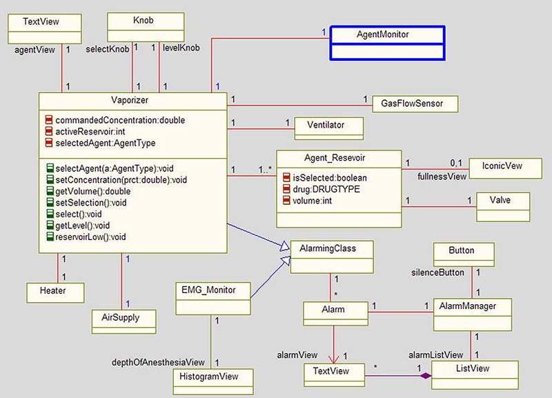
Figure 6 shows a typical nanocycle scenario in a medical device
that provides automatic drug delivery. Figure 7 shows the internal design,
which raises the question, "Is it right?" To determine the answer,
the model is executed, revealing that the vaporizer has no way of knowing the
current drug level in the breathing circuit. The scenario is elaborated in
Figure 8 by adding design elements to address this concern. Furthermore, an
AgentMonitor class is added to the design in Figure 8 to monitor the current
drug level in the breathing circuit. This object is added to the sequence
diagram in Figure 9, and the model is re-executed.
|
|

|
|

|
|
|
|

Building an executable application for a variety of target
platforms is easy within the UML environment provided by high-end tools;
however, the ability to easily stimulate the application and monitor feedback
is not automatic. Creating a front-end panel and the infrastructure to tie it
to the application can take significant time and effort.
A new type of collaborative tool solves these challenges by
autogenerating a panel (for example, an interactive Web page) that can be used
at any point to stimulate the model and provide feedback on its execution. This
type of development tool provides the ability to easily create a prototype for
customers and management as well as convey concepts and visualize
customer-driven ideas. The infrastructure that ties to the model is generated
with the click of a button, and the panel can be enhanced to create a realistic
display, resulting in a powerful rapid prototyping environment.
Requirements-based testing
Requirements-based testing tools enable design-level testing
using standard UML sequence diagrams. The test environment binds actual
instances to instance parameters and actual values to passed operations
parameters as necessary. Either the test environment or the user plays the role
of the collaboration boundary. White-box testing drives the design according to
expected scenarios' inputs, monitors the design during execution to make sure
it executes as expected, and highlights cases where the expected scenario and
actual scenario are not the same.
Automatic model-driven test generation analyzes the model and
code to generate test cases for complete test coverage, resulting in
high-coverage UML model testing. Test cases provide full coverage for states,
transitions, operations calls, and events used in the model. Furthermore, the
automatic test generation tool is flexible enough to read user-defined test
cases, analyze the coverage, and then automatically generate new test cases for
the uncovered portion of the design.
Creating test scenarios on the host and running them
throughout the development process offers significant automation for regression
testing. In addition, running the test cases on the target allows developers to
detect situations where the behavior on the target differs from the design's
intended behavior. Test cases can be exported for scenario-based testing or to
third-party tools for test execution and code-level coverage analysis.
Automatic test generation, which is typically used for
performance, stress, and coverage testing, benefits the requirements team as
well as the development team. Systems engineers using formal specifications
with state machines can generate tests that cover all transition paths in their
UML use case requirements specification model. This technology allows software
design and verification engineers performing unit and integration testing to
generate tests more quickly. Automatic test generation is not designed for
testers who are unfamiliar with UML or the design or those who do not get
involved with testing until fairly late in the process.
Both scenario-based and automatically generated tests are
included as an integral part of system development. Following successful unit
test, peer-reviewing the model provides design information to other team
members and enables them to comment and critique. Once the tested and verified
subsystems are produced, they are integrated with specific artifacts from other
engineering disciplines into a system prototype validated against system
requirements, which include new requirements added during the incremental
development cycle. System prototypes become increasingly complete as more of
the remaining capabilities are added over time until the system meets the
entire set of requirements necessary for product release. At this point, the
engineered system is passed to final acceptance testing and released to the
customer.
Less costly, better quality systems
TDD offers several important advantages. It simultaneously
tests the model to ensure that it is logically correct and tests the system to
ensure the QoS requirements are met. Primary test vectors are virtually free
because they are automatically derived from requirements scenarios.
Another advantage of testing at the model level is defect
identification using model concepts, which simplifies troubleshooting because
model concepts are much more intuitive. TDD thus simultaneously lowers costs
for defect removal while increasing the finished product's quality.
Bruce Powel Douglass
is chief evangelist for Telelogic, headquartered in Sweden and Irvine,
California. With more than 30 years of experience designing safety-critical
real-time applications, he has designed and taught numerous courses on object
orientation, real-time, and safety-critical systems development. Bruce
currently serves as an advisory board member for the Embedded Systems
Conference and previously served as cochair for the Real-Time Analysis and
Design Working Group in the OMG standards organization. He has written 13
books, including Real-Time UML Workshop,
Doing Hard Time, and the forthcoming Real-Time Agility, scheduled for release this
fall. Bruce has a BS in Physical Education and an MS in Exercise Physiology
from the University of Oregon as well as a PhD in Neurocybernetics from the
University of South Dakota School of Medicine.
Telelogic
703-938-2711
[email protected]
www.telelogic.com


