
Worried About Heat in Your I/O Module? No Need to Sweat
March 22, 2019
Story

In this design solution, we?ll examine the limitations of traditional ?discrete? design of the digital input (DI) component of the I/O module.
Introduction
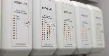
Sitting at the boundary between a high-voltage, harsh, noisy factory-floor environment and a sophisticated, low-voltage programmable logic controller (PLC) is the oft-neglected and humble digital I/O module (Figure 1). The design of these modules is challenging due to the variety of application uses and the common requirements for electrical isolation, small size, and low-power consumption. In this design solution, we’ll examine the limitations of traditional “discrete” design of the digital input (DI) component of the I/O module, concentrating on heat generated from high power consumption. We then propose an alternative that offers several unique advantages when compared to the traditional approach.
The IEC 61131-2 standard for PLCs specifies three different types of digital input receivers: Types 1, 2 and 3. The standard states that ideal implementations for Type 3 should draw as close to 2mA as possible in the logic-high state and have voltage transition thresholds between 5V and 11V.
A typical discrete implementation of a Type 3 receiver is illustrated in Figure 2. Isolation is provided using an optocoupler. The received input signal threshold is set using voltage-divider R1 and R2 and then interpreted as a logic-high or logic-low using a voltage comparator with hysteresis (to provide noise immunity).
Digital Input Design
Digital I/O modules typically consist of 16 or 32 channels of either digital inputs or digital outputs (DO). Some modules allow channels to be configured as either a DI or a DO as required. Digital inputs are used with PLCs and motor drives to receive digital signals from field sensors and switches. Because the field voltages (24V or higher) are much higher than the PLC logic voltage (5V or less), a key requirement of the DI is to provide electrical isolation between the two domains for safety reasons.
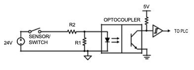
This circuit configuration is inefficient since it only uses resistors to limit current consumption (which is obviously voltage dependent). For a 32V input, this configuration can consume over 10mA.
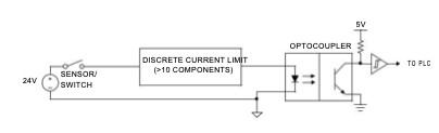
In compact multi-channel modules, power consumption (and its associated heat dissipation) is a critical concern. Therefore, a more sophisticated form of current limitation must be implemented. A custom-designed current-limiting circuit can be built but would require more than 10 discrete components: a TVS, resistors, a transistor, a voltage reference, and a comparator. Current consumption for this solution would typically be 5mA—over twice the ideal 2mA for a Type 3 input—and the board area consumed by such a design is relatively large. Another disadvantage of this approach is that while current-limiting is more accurate than using a simple resistor-divider, the range of digital input voltages across which it functions can be quite limited.
Reducing Power and Size
A superior alternative to the discrete-component approach is to use an integrated solution. This has several advantages over the discrete solution. Current consumption is reduced to levels much closer to the ideal specification for Type 3 inputs, and current limiting becomes much more accurate, both of which help reduce heat dissipation. An integrated device can also function over a wider range of input voltages than a discrete solution and has the potential to reduce board area.
The parasitically powered digital input shown in Figure 4 is an IEC 61131-2-compliant, fully integrated digital input that translates a 24V digital industrial input to a 2.6mA (max) current for driving optical isolators. Power consumption is approximately 65mW (24V 2.6mA) for a single DI channel, which is more than a factor of three reduction when compared to the 210mW (24V × 8.75mA typical) for a current-limited discrete implementation. Current consumption is limited to a range between 2.1mA to 2.6mA across the full voltage input range, a variation of only 25 percent. This is a vast improvement over discrete solutions where current can vary by more than 100 percent. It is also an improvement over other integrated solutions that have a current range from 2.3mA to 3.4mA per channel, a variation of 35 percent. Voltage thresholds and current levels are compliant with both Type 1 and Type 3 inputs. The device is compliant with 48V inputs with the addition of external resistors. It provides for a maximum operating voltage of 60V, compared to only 45V allowed by other typical integrated solutions. Another appealing feature is that the operating current is drawn from the input signal, eliminating the need for a dedicated field-side power supply, which simplifies board layout.

The small 6-lead SOT23 package, measuring 2.8mm × 2.9mm, reduces the required board area by up to 40 percent compared to the discrete-component implementation. Depending on the desired application, this part can be configured either to source or sink current. It has a fast 250ns response time which supports high-speed DI devices, and 1kV surge protection (using an external TVS) ensures robustness even in the most challenging industrial conditions.
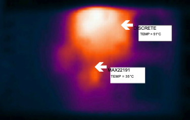
The thermal image in Figure 5 shows the effective heat reduction when using this IC, when compared to a discrete DI implementation. Both solutions are on the same board, and the temperature differential recorded was > 15°C for a single 24V input signal in a typical lab environment. The potential for heat reduction in the confined space of a multi-channel module is obvious.
Conclusion
We reviewed the limitations of a typical discrete component implementation of a digital input for PLCs and then compared its performance to an almost completely integrated approach. We presented a parasitically powered digital input IC that provides a smaller, lower power solution with much less heat generation. It is suitable for process automation, industrial automation, motor controls, individually isolated inputs and applications with current sinking/sourcing inputs.
Glossary Terms
PLC: Programmable logic controller. A ruggedized, microprocessor-based system that provides factory or plant automation by monitoring sensors and controlling actuators in real time.
TVS: Transient voltage suppressor. Semiconductor device designed to protect a circuit from voltage and current transients. Typically implemented as a large silicon diode operating in avalanche mode to absorb large currents quickly.
IEC 61131-2: International electrotechnical commission standard for PLCs
LDO: Low-dropout linear regulator. A linear voltage regulator that will operate even when the input voltage barely exceeds the desired output voltage.
Learn more:
MAX22191 Parasitically Powered Digital Input
Michael Jackson has over 20 years’ professional experience as an Analog IC Design Engineer and holds the position of Principal Technical Writer at Maxim Integrated. He has a MSEE from Dublin City University.
Sean Long is Director, Applications for the Industrial and Healthcare Business Unit at Maxim Integrated. Sean joined Maxim in May 2012. He has a BSc Electrical and Electronic Engineering from Aston University, Birmingham.


