
In-lab FPGA verification is here to stay
April 02, 2015

I remotely attended the Verification Futures conference, organized by TVS in the UK (you can find the slides on their web site) where NMI's Doug Amos...
I remotely attended the Verification Futures conference, organized by TVS in the UK (you can find the slides on their web site) where NMI’s Doug Amos presented the results of a survey conducted in 2014 about FPGA usage in the UK and Ireland. One aspect that struck me is that the most commonly used FPGA verification techniques are:
- In-system testing in the lab
- Various simulation strategies
- Manual RTL code reviews
In addition, techniques familiar to ASIC and SoC engineers, like formal equivalence checking and assertion-based verification aren’t widely used.
A few weeks later, I was at a technical seminar organized by one of the major FPGA vendors in the Netherlands. I wanted to check on the above results with some of the attendees during the lunch. I found it interest that they ALL used in-lab testing on target hardware for FPGA verification. Yet, modern FPGA design flows rely on a wide array of techniques.
Today, FPGA designs are made of a large number of IPs. Careful floorplanning is sometimes required. FPGA simulation is sophisticated, with common use of code coverage and even sometimes constrained random stimulus generation. While VHDL and Verilog are widely used, system-level language is also put to use for FPGA design. Reaching higher quality designs faster is of course the main purpose of this collection of tools.
So when exactly do engineers use in-lab testing for FPGA design and verification? As one of my lunch companions said, “This is when we put things together for real that virtually anything can go wrong.”
This engineer has a point. More time can be spent on exploring all the corner cases of a specification, making sure that everything is covered, including what a design should and shouldn’t do. More time can be spent both on making sure that the FPGA environment is properly modeled and on simulation.
However, at some point in the process of designing an FPGA, there comes the difficult trade-off between spending more time on specs and models and trying the system in its real environment. This is key because, even with the best methodology and tools, the finest piece of IP fails sometimes in specific environments. That’s partly because not all the design pieces are designed with the same level of quality and partly because the complexity of modern FPGA-based systems is difficult to master.
FPGA in-lab testing is also a matter of economics. ASIC and SoC designers don’t have the ability to do in-lab testing before millions of dollars is spent in NRE. The risk of wasting so much money is a strong incentive for investing in anything but doing verification in the lab.
Conversely, the cost of setting up in-lab FPGA verification is quite low. It’s also attractive for managers to see that a product is in the lab, tested in a real environment, and closer to the product launch. This is why your manager might be more inclined to let you go in the lab rather than spending a six figures on a state-of-the-art emulator.
For the engineer, in-lab testing has two main advantages: it closely (or exactly) matches the target system environment and it runs at system speed. Hence, it eliminates modeling headaches, and allows system operating times that can’t be reached easily with other techniques.
When asked what they use at this stage of the design flow, the answers are (unsurprisingly?) similar. Two techniques still prevail: either they connect a logic analyzer to some of the FPGAs I/Os or they use an embedded logic analyzer, as shown in Figure 1.
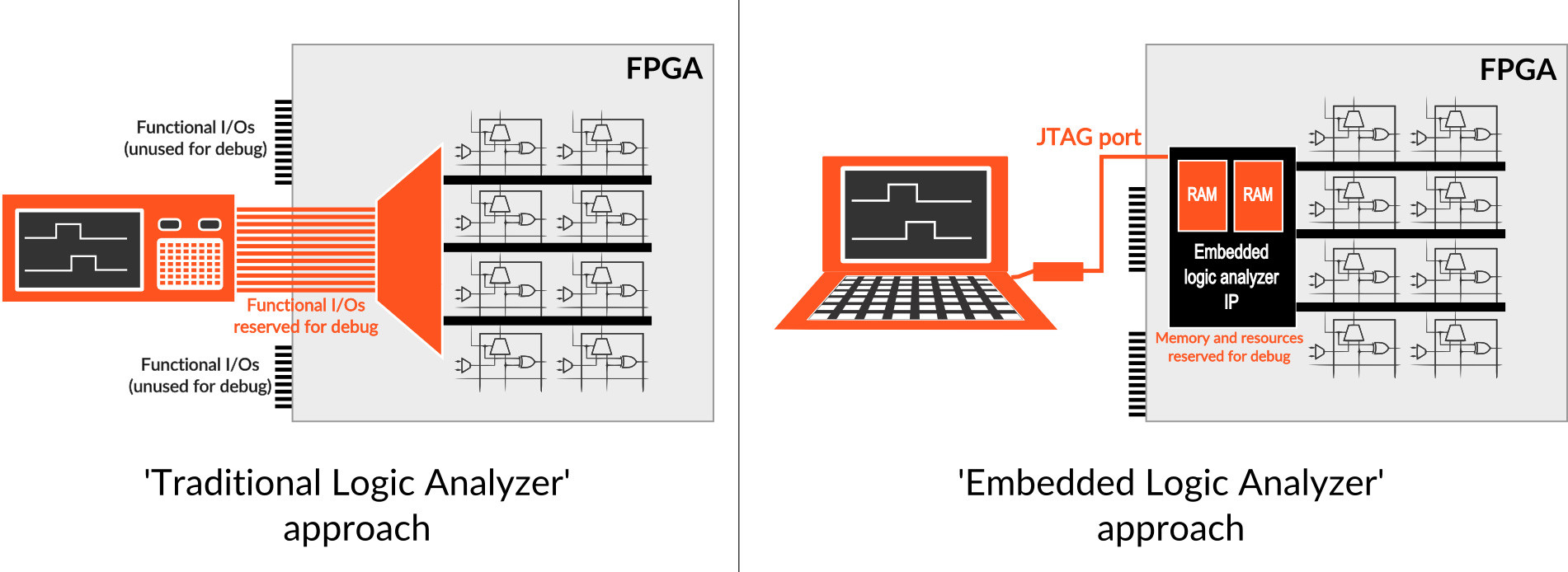 Figure 1 (Click to enlarge)
Schematically, using a traditional logic analyzer to debug FPGAs consists in making a special FPGA configuration where internal nodes are routed onto some of the chip’s functional I/Os. These I/Os are physically routed onboard to a connector on which the logic analyzer can be hooked. This approach uses the ability to reconfigure the FPGA to route diverse groups of internal nodes to the same set of physical I/Os. Multiplexing groups of nodes helps reduce the number of FPGA synthesis and implementation iterations. The observed node’s evolution is stored in the logic analyzer for further analysis.
Conversely, using an embedded logic analyzer consists of reserving FPGA memory resources to store the FPGA node’s evolution. Subsequently, this memory is read using the device’s JTAG port. The collected traces can be viewed on a PC, usually with waveform viewer software.
These techniques provide some visibility into the design to better understand why a bug occurs. However, this is precisely why these techniques don’t work. Traditional and embedded logic analyzers don’t provide sufficient visibility assuming there’s a reasonable mobilization of FPGA resources. In other words, FPGAs have become so complex that there are just too many things you’ll want to observe during the debug process.
The increasing complexity of FPGAs brings new challenges at all level of the design flow. Hence, rather than abandoning the in-lab technique because of its poor visibility, it’s worth exploring what should be done to improve it. This means (much) more observability at equal or lower cost on the FPGA resources. The actual cost of FPGA resources really depends on the context and design.
In this post, we assume a standard number FPGA I/Os and FPGA memory is used. Using more I/Os can be costly because it requires more PCB real estate and may force the use of a bigger FPGA package. Using more memory for debug can be costly because it may not leave sufficient RAM for the FPGA functionality and could result in the need for a a bigger FPGA.
Figure 2 shows the relative positions of the logic analyzer and the embedded logic analyzers on a two-axis resources chart. The area occupied by each solution shows the relative order of magnitude of the trace memory they provide, which is a good measure of the provided observability.
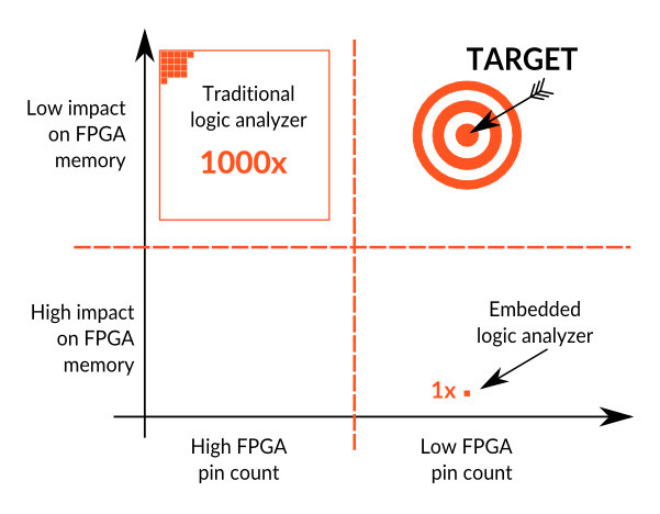 Figure 2 (Click to enlarge)
A better solution for in-lab FPGA debug should hit the “target” position on the chart and provide more observability.
Frederic Leens is the CEO and founder of Byte Paradigm and Yugo Systems. Byte Paradigm provides design services and test and measurement tools to the embedded electronics industry, while Yugo System provides FPGA and programmable-logic debug solutions. Previously, Leens worked as an ASIC, SoC, and FPGA engineer for industries ranging from avionics to medical electronics.


