
100 Gigabit Ethernet tackles backplanes and copper cables
December 01, 2011

The implementation of the IEEE 100 Gbps Backplane and Copper Cable Task Force precipitates the creation of specifications to increase signaling rates...
Contemplate this definition from Wikipedia: “Metcalfe’s law states that the value of a telecommunications network is proportional to the square of the number of connected users of the system (n2).” Consider also this famous saying attributed to Benjamin Franklin: “Time is money.” The summation of Metcalfe’s law and Franklin’s statement can be used to describe the progression of Ethernet during the past 35 years, as higher networking speeds have enabled large volume deployment of the lower-speed ports associated with computing. Gigabit Ethernet (GbE) helped enable high-volume deployment of 100 Mb Ethernet, and 10 GbE helped enable high-volume deployment of GbE. Today, the introduction of 40 GbE and 100 GbE will enable high-volume deployment of 10 GbE.
Ratified in June 2010, IEEE Std 802.3ba-2010 defines 40 GbE and 100 GbE operation, as well as several physical layer specifications. Table 1 summarizes the different physical layer specifications developed under this project.
|
|
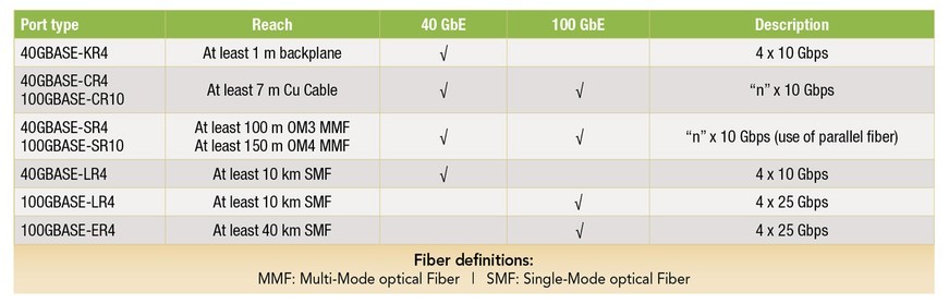
The two physical layer specifications related to electrical transmission across a copper medium are the -KR (backplanes) and the -CR (Cu Cable) specifications. Two observations can be made from this table. First, both of these physical layer specifications are based on an “n” lane by 10 Gbps approach. Second, no physical layer specification for 100 GbE over a backplane is defined, implying that a 10 lane by 10 Gbps approach was not deemed acceptable for a 100 GbE backplane specification.
Expanding the 100 GbE physical layer specifications
Since the ratification of the 40 GbE and 100 GbE specifications, the Ethernet community recognized the need to grow the family of 100 GbE physical layer specifications and add one to address operation across a backplane. Several factors contributed to this realization[1]:
- As front-panel I/O capacities based on form factors supporting 10 Gbps, 40 Gbps, and 100 Gbps were considered, line card capacities ranging anywhere from 400 Gbps to 3.2 Tbps were observed. Based on these line card capacities, overall backplane capacity requirements ranging up to 45 Tbps were calculated.
- Building backplanes to support these line card and backplane capacities becomes increasingly challenging from a feasibility and cost perspective when using just a x10 architecture based on 10 Gbps electrical signaling, as compared to a x4 architecture based on 25 Gbps electrical signaling. Simply put, the sheer number of differential traces drives up the number of connector pins as well as the number of PCB layers.
- During the rate debate between 40 GbE and 100 GbE, it was noted that server bandwidth capacity was doubling approximately every 24 months. Based on this observation, servers would be supporting 100 GbE by 2017. The backplanes supporting these servers, however, would be shipped in systems prior to this timeframe. Thus, to ensure that these backplanes would be upgradable to 100 GbE, it would be necessary to develop a standard defining a backplane channel capable of supporting 25 Gbps signaling for implementing a x4 architecture to support 100 GbE.
In addition, as 10GBASE-KR provided the basis for development of the -CR family of physical layer specifications, it was realized that the reduction in the number of lanes enabled by increasing the lane rate from 10 Gbps to 25 Gbps would also be beneficial for copper twin-ax cable assemblies. By decreasing the number of differential pairs from 10 to four, improvements in cost, port density, and ease of routing can be achieved.
Therefore, the true challenge in developing the physical layer specifications for 100 GbE across backplanes and copper cables will be increasing the signaling rate across a given lane from 10 Gbps to 25 Gbps. Despite this dilemma, numerous potential options can be explored as part of the overall solution.
The channel
For physical layer specifications, the channel is ultimately the problem statement. The insertion loss, its deviation, return loss, and the relationship between crosstalk and insertion loss all combine to define the channel’s performance limitations. While continuing improvements in connector technology, PCB materials, and board manufacturing improve channel quality, they usually come at a cost. Such backplane-related efforts typically result in a discussion of supporting legacy backplanes that are deployed today versus Greenfield backplanes that can take advantage of the latest technologies. However, more challenging channels can drive up the complexity and power of the circuitry used to solve the problem.
The channel for a copper cable has its own share of challenges. Connector technology, PCB materials, and board manufacturing will improve the quality of the channel that resides on a host board, but budgeting loss to the host board traces will consequently reduce the amount of loss associated with the cable assembly, which translates into shorter cable reaches.
Modulation
Non-Return-to-Zero (NRZ) is the incumbent signaling scheme. The 10GBASE-KR solution is capable of approximately 25 dB insertion loss at the Nyquist frequency of 5.15625 GHz. It is anticipated that an NRZ scheme at approximately 25 Gbps would support a channel insertion loss of approximately 25 dB to 30 dB insertion loss at 12.9 GHz without the use of Forward Error Correction (FEC). For high-volume applications or legacy backplanes that will exist in the field at the time the standard is ratified, such loss targets might prove too costly. Therefore, some are suggesting that the group should consider developing a 4-level pulse amplitude modulated specification in addition to an NRZ solution. It has been suggested that a PAM-4 solution would support a channel insertion loss of approximately 30 dB insertion loss at roughly 7 GHz.
Equalization
Various forms of equalization – from transmit feed-forward equalization and waveshaping to continuous timeline equalization to receiver decision feedback equalization – are employed to overcome the various deficiencies within a given channel. The appropriate type of equalization is dependent on the modulation scheme and target channel. It is important to understand that equalization must be optimized, and that it is possible to overequalize a channel.
FEC
FEC can improve overall link performance at the cost of added complexity and latency. Therefore, the interaction between different FEC proposals and the IEEE 802.3ba-2010 architecture must be evaluated to determine the solution that will have optimal latency at an acceptable level of complexity. Proposals for 6 dB or more of coding gain have been proposed, and it is anticipated that any solution capable of driving 100 GbE across a backplane channel that is 1 m long will require some type of FEC.
Laying the foundation for next-generation networking
The development of these new physical layer specifications will be driven by the IEEE P802.3bj 100 Gbps Backplane and Copper Cable Task Force, which was formed in September 2011. The objectives for this project include:
- Support full-duplex operation only.
- Preserve the 802.3/Ethernet frame format utilizing the 802.3 Medium Access Control (MAC).
- Preserve the minimum and maximum frame size of the current 802.3 standard.
- Support a bit error rate of better than or equal to 10-12 at the MAC/private line service interface.
- Define a 4-lane 100 Gbps backplane PHY for operation over links consistent with copper traces on “improved FR-4” (as defined by IEEE P802.3ap or better materials to be defined by the task force) with lengths up to at least 1 m.
- Define a 4-lane 100 Gbps PHY for operation over links consistent with copper twin-axial cables with lengths up to at least 5 m.
In addition to these objectives, presentations regarding energy efficiency for the new 100 GbE physical layer specifications are being considered. These presentations build on the Energy Efficient Ethernet concepts defined as part of IEEE 802.3az-2010, which defines a low-power idle state during low utilization periods.
As the task force has begun the process of hearing and selecting technical proposals that will form the basis of the specification, it is anticipated that this will continue throughout 2012, with the final ratification of the standard expected in early 2014. These new specifications will provide the underlying technology that will enable the next generation of networking equipment targeting higher-density 10 GbE, 40 GbE, and 100 GbE port densities, as well as lay the interconnect foundation for blade server systems targeting 100 GbE.
To learn more about the IEEE P802.3bj 100 Gbps Backplane and Copper Cable Task Force and find out how to participate, visit www.ieee802.org/3/.
References:
[1] 100GbE Electrical Backplane/Cu Cabling Call-For-Interest, www.ieee802.org/3/100GCU/public/nov10/CFI_01_1110.pdf, November 9, 2010.
Dell www.dell.com IEEE [email protected] www.ieee.org


