
Optimizing microcontroller power efficiency for ultra-low-power designs
February 01, 2010

For compact, battery-operated devices, power consumption must be coordinated across the entire system.
Designers typically optimize device power consumption by reducing active processing time and increasing how long microcontrollers (MCUs) can reside in sleep mode. With the rise of ultra-low-power applications, however, this approach no longer suffices.
For devices such as electric toothbrushes, personal media players, remote controllers, wireless sensors, and a wide range of other portable and handheld devices, power management needs to be implemented at all levels of a system. By optimizing power consumption through efficient single-cell voltage conversion, utilizing multiple current modes, introducing smart battery management, and implementing power-saving techniques at the application level, power consumption can be coordinated across an entire system.
Efficient voltage conversion
Many ultra-low-power applications are moving to single battery cell architecture to decrease device cost, size, and weight. Reducing the power supply to a single cell is an attractive option because it simplifies battery holder mechanics and results in significantly smaller and lighter products.
While the voltage from a single battery cell usually ranges from 1.2 V to 1.5 V when fully charged, cells can drop below 1 V while still possessing a substantial amount of usable energy. Driving motors, LEDs, and even the microcontroller itself from a single cell requires a regulator to boost the available voltage to appropriate levels.
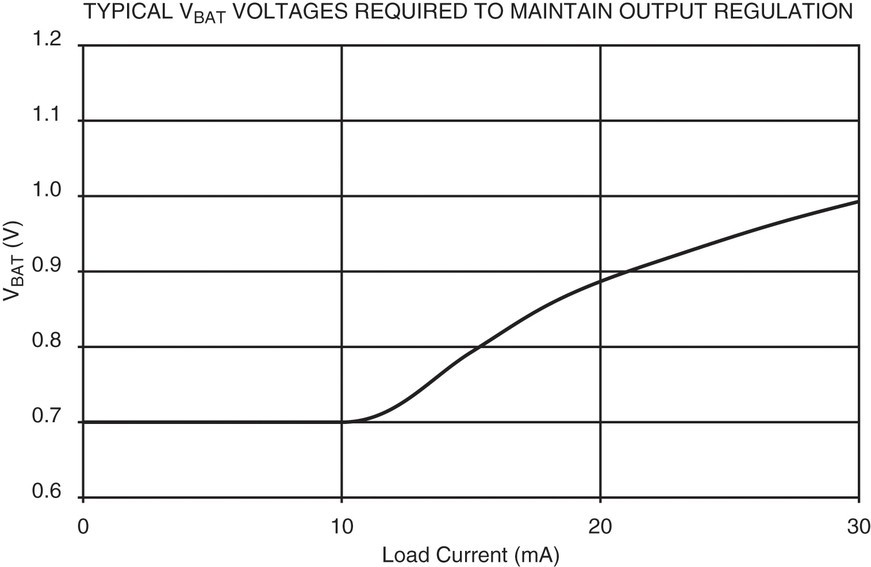
The ATtiny43U has an integrated regulator that can boost voltages as low as 0.7 V (see Figure 1), allowing discharging to continue closer to the end of a cell’s reserves. This integrated regulator offers a 1 microamp (typical) idle current, automatic start as soon as sufficient voltage is available, and support for any battery technology, enabling developers to use 1.6 V alkaline or silver oxide, 1.5 V Li-ion, 1.4 V zinc-air, and 1.2 V NiMH and NiCd, among others.
|
|
Boost and low current modes
High current capacity without external drive circuitry is also important for many applications. The ATtiny43U’s boost regulator can drive up to 30 mA, enabling direct control of high-brightness LEDs and small motors. Figure 2 shows the ATtiny43U’s conversion efficiency for particular load currents based on remaining charge.
|
|

As seen in Figure 2, high current operation is less efficient than when running at a lower current, but most high current applications do not need to operate in high current mode continuously. If the architecture is locked into a high current mode, then these devices will operate at reduced efficiency even when the device only requires a low current draw.
To preserve efficiency, the MCU must be able to support multiple operating modes. When the device requires high current and tightly regulated Vcc, the MCU and regulator will operate in a regulated mode. When motors or other peripherals are not in use, and the load current drops down below 0.6 mA, the regulator automatically switches into a low current mode, performing more efficient power conversion.
Additionally, at light or no loads the converter in regulated mode will periodically reach its duty cycle low limit. By automatically dropping into low current mode, the converter stops switching and reduces current consumption to a minimum while still remaining active (see Figure 3).
|
|

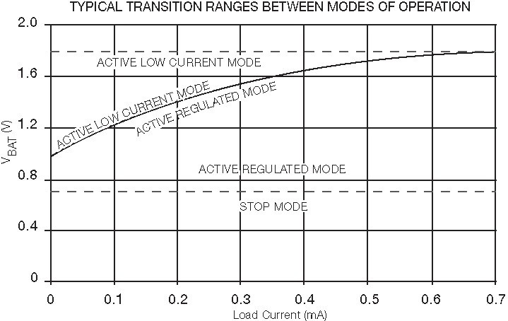
In the main mode of operation, active regulated mode, output voltage remains stable within 3 V ±100 mV. Also note that the typical transition voltage changes as the energy in the cell is depleted (see Figure 4).
|
|
Smart battery management
Rechargeable batteries require careful monitoring and charging control within set limits to ensure safe usage and optimum operating life. Different battery chemistries have different voltage thresholds to which they can be safely charged and discharged.
The ATtiny43U’s firmware can monitor the battery voltage using the built-in Analog-to-Digital Converter (ADC) and decide when to put itself in stop mode, thus thoroughly draining disposable batteries while ensuring the maximum life of rechargeable cells over multiple recharging cycles.
While automatically shutting down an MCU protects rechargeable cells, an abrupt loss of power may not be acceptable from an application perspective. For example, shutting a camera down suddenly will leave the lens exposed and vulnerable. Using the ADC to measure the battery voltage at regular time intervals gives the application a chance to place devices into a safe configuration before shutdown.
More power-saving techniques
Many applications add an MCU as a secondary processor to assist the main application processor, offloading tasks such as updating a display, monitoring a keyboard, operating small motors, and intelligently managing smart batteries. Using an MCU this way enables the application processor to sleep longer uninterrupted, resulting in substantial power savings.
Ultra-low-power MCUs also require multiple sleep modes. For example, a sensor application may monitor temperature until it exceeds a threshold. Keeping the entire MCU in active mode during monitoring consumes more power than is actually necessary. Support for different sleep modes that allow developers to shut down different parts of the device enable better power conservation (see Table 1).
|
|

Many other innovations in the ATtiny43U architecture increase power efficiency in both active and sleep modes:
Low-power brownout detection
While zero-power brownout detectors consume no power, they are also slow to respond and can require a full millisecond to detect a below-threshold voltage, thus leaving the MCU at risk. Alternatively, a sleeping brownout detector can identify brownout conditions in 2 microseconds while drawing only 20 microamps.
Digital input disable registers
Multiplexing inputs to a peripheral such as an ADC helps low-pin-count devices, but when voltages in the range of Vcc/2 are applied, the transistors comprising the input buffer will experience current leakage. The use of dedicated input disable registers with one disable bit per analog input enables developers to disable individual input buffers to prevent leakage.
Power reduction register
While multiple sleep modes simplify power management, they often turn whole blocks of peripherals on or off. A power reduction register gives developers full control to turn off individual peripheral modules. Disabling one peripheral module can result in a reduction of 5-10 percent of the total power consumption in active mode and 10-20 percent in idle mode.
Flash sampling
Traditional flash is designed to always be enabled while in active mode. At lower clock speeds, however, the flash read time will be less than the clock period. Flash sampling enables the flash on the order of 10 ns to sample the array’s contents and then immediately disables it, reducing average power consumption.
Seeing the difference
Development kits provide an effective means for testing an MCU’s efficiency under real-world operating conditions. The ATtinyx3U top module attaches to the ATSTK600 development board (see Figure 5). Using this kit, developers can test the limits of single-cell operation, profile power consumption while directly driving a high-brightness LED, and drive the integrated boost regulator’s auto shutdown and power-on features to tune power thresholds to utilize the maximum capacity of cells within safe parameters.
|
|

MCUs integrating an on-chip regulator with configurable modes efficiently bridge the gap between the minimum supply voltage of the MCU and typical output voltages of standard single-cell battery technologies, enabling developers to minimize power consumption based on available load conditions and battery voltage. With only one battery, no external regulator, the ability to drain cells down to 0.7 V, and high current capacity for LEDs and small motors, designers can build compact, cost-effective, battery-operated devices that are truly ultra-low-power.
Atmel 408-441-0311 [email protected] [email protected] www.atmel.com


