
Handle bandwidths with 4 mA to 20 mA current inputs using HART compatibility
March 19, 2015

Different applications requires different analog inputs. HART-enabled techniques simplify the design process. It's not uncommon to see 4 m Ato 20 mA a...
Different applications requires different analog inputs. HART-enabled techniques simplify the design process.
It’s not uncommon to see 4 m Ato 20 mA analog current loops in process plant or factory environments. While the basic signaling is the same in these varied applications, the bandwidth requirements differ significantly. Factory control systems may require loop bandwidths of 100s of hertz from position and displacement sensor, while typical process control systems only require update rates of a few hertz and are often HART (highway addressable remote transducer) enabled. The HART protocol allows for bi-directional 1.2/2.2 kHz FSK (frequency shift keying) modulated digital communication over traditional analog 4 mA to 20 mA current loops. Designing a 4 m A to 20 mA input that caters for both scenarios can be challenging. The circuit diagram in Figure 1 shows a traditional approach to implementing a HART-enabled analog input.
|
|
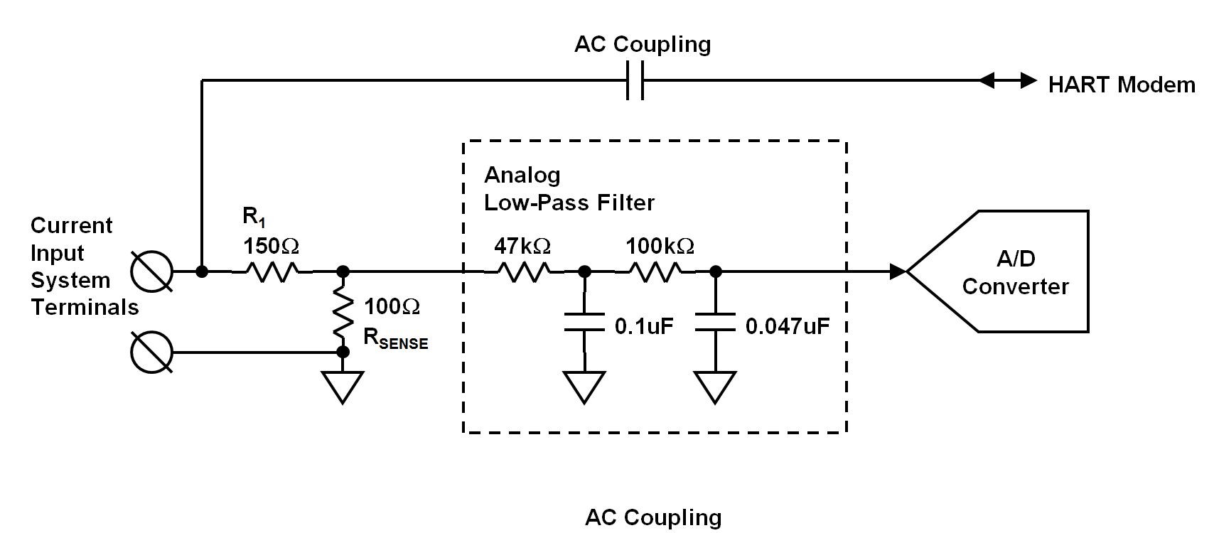
In the diagram, R1 and RSENSE provide a 250-Wohm system terminal impedance. The HART FSK signal is AC-coupled from there to a HART modem. The 4 mA to 20 mA analog signal is converted by a precision 100 W RSENSE resistor to a 0.4 V to 2 V signal. The analog low-pass filter then attenuates the HART FSK component from the analog signal before passing it to an A/D converter. The second-order low-pass analog filter has a bandwidth of 25 Hz and -40 dB/decade roll-off. This circuit complies with HART specifications, and provides attenuation of HART FSK signal to level over -60 dB below the 4 mA to 20 mA full scale, ensuring less than 0.1 percent disturbance of the input by the HART FSK communication.
On the other hand, this analog low-pass filter takes almost 70 ms to settle within 0.1 percent after a full-scale step on the system input. The long settling time and low bandwidth wouldn’t be suitable for systems where fast operation is required and HART communication isn’t needed. The analog filter could indeed be bypassed, but that would require additional analog circuitry, such as switches or multiplexers. Figure 2 shows an alternative approach to the HART enabled analog input.
|
|

Similar to the previous circuit, the HART FSK signal is AC coupled from a 250 Ω input impedance, and the 4 mA to 20 mA signal is converted by a precision 100 W RSENSE resistor to a 0.4 V to 2 V signal. In this circuit, however, a considerably lighter low-pass filter limits the signal’s bandwidth to about 27 kHz, just to provide system immunity and electromagnetic compatibility (EMC). The filter settles to 0.1 percent in 40 µs after a full-scale step on the system input.
This signal is passed to a sigma-delta A/D converter with a built-in digital filter, such as Analog Devices’ AD7173. The digital filter can be programmed for either slower operation and optimum HART FSK signal rejection, or fast operation when fast analog input functionality is required.
The AD7173 has many modes of operation. One mode suitable for rejecting HART FSK signal is a SINC3 filter with a notch set to 400 Hz, or sub-multiples, which provides a deep filter notch at the lower HART FSK frequency (1.2 kHz) and significant attenuation at the higher frequency (2.2 kHz). The graph in Figure 3 shows the frequency response of this digital filter and its comparison with the analog filter from Figure 1.
|
|

Unfortunately, the real world isn’t that simple. When a complete message is sent via HART, the HART FSK modulated signal spectrum not only contains energy at the base modulation frequencies, but will also contain components between, below, and above the 1.2 kHz and 2.2 kHz carrier. Figure 4 shows a typical spectrum of the HART FSK message on the A/D converter input as well as the spectrum when attenuated by the SINC3 filter with a 400 Hz notch. In this case, the master is sending HART command 3 and a slave is responding to that command.
|
|

From Figure 4, it’s apparent that a portion of the HART message, especially at the lower frequencies, can still be present in the A/D output data. That said, the digital filter settings can easily be altered to set the right balance between the input speed and rejection of the HART FSK signaling. Figure 5 shows the system performance, measured as a percentage error with respect to the 4 mA to 20 mA full scale, versus the system speed for the analog filter (Figure 1) and the SINC3 digital filter (Figure 2).
|
|

The analog filter is fixed in hardware and has a fixed settling time. For fast-changing analog signals on the system input, the analog filter output error is dominated by its slow settling. For example, if the system input was changing full scale every 40 ms, the filter output wouldn’t settle closer than 1 percent of the correct value. For the slow input signals, the analog filter output error is dominated by its ability to reject the low frequency components of the HART FSK signaling. This error was measured as about 0.09 percent of the 4 mA to 20 mA full scale for a typical HART command 3 message.
Alternatively, the digital SINC3 filter’s settling time is a parameter set by the user, and the error on the filter output caused by the HART FSK signaling corresponds to the filter setup. For example, the SINC3 filter with the 400 Hz notch corresponds to a 7.5 ms settling time, and when communicating the HART command 3, the measured disturbance in the A/D result was less than 0.4 percent of the 4 mA to 20 mA full scale. In a system with four analog inputs, the SINC3 filter is sequentially switched between the channels. The same SIN3 filter with a 400 Hz notch now needs 4 x 7.5 = 30 ms to scan all four channels. That is why the plot shows the same ~0.4 percent error at 30 ms for the four-channel system.
For a more accurate 4 mA to 20 mA input, the SINC3 filter can be set to a 30 ms settling time, which corresponds to a 100 Hz notch and it rejects the HART signal to less than 0.1 percent of the full scale. If speed is more important, the SINC3 filter with 6 ms settling (~500 Hz notch) still rejects the HART communication signal below 0.5 percent of the 4 mA to 20 mA input. And if speed is the only requirement and HART communication isn’t needed, the AD7173 discussed previously can sample over 31ksamples/s with a settling time of 161 µs/channel.
The traditional analog low-pass filter is easier to understand and for the price of few more components per channel on the board may, in some cases, give better analog input performance when implemented in a multi-channel system. On the other hand, the digital SINC filter integrated on a sigma-delta A/D converter enables significant flexibility, which can be offered all the way down to the end system user. The digital solution requires less hardware and, if setup properly, its performance in filtering HART FSK signaling is better than the analog solution in single-channel systems and comparable or better in up to four-channel systems.


