
FM Lidar Versus the Alternatives: Comparisons and Design Tradeoffs
March 04, 2019
Story

The need for lidar in the autonomous vehicle sensor stack led to an explosion of investment from OEMs between 2016 and 2018.
The need for lidar in the autonomous vehicle sensor stack led to an explosion of investment from OEMs between 2016 and 2018. More than 70 companies received a total of over $1 billion to bring competing lidar approaches to the market. While these technology bets will take years to mature into complete products, the glut has led analysts and reporters into consistent speculation around who the winners and losers will be.

Many writers focus on beam scanning technology as a primary axis for comparison. Is a given product mechanical, solid-state, MEMS, flash? The fixation on this technological differentiator is likely a vestige of early market movers making aggressive promises to deliver ultra-low cost solid-state scanning lidar. This focus on scanning technology has distracted from discussion of more fundamental questions: how does the lidar measure distance? Can it measure velocity? And – assuming chip-set integration is required for scalability to automotive volumes - what are the implications of one approach over another at scale?
Pulsed time-of-flight or amplitude modulated, “AM,” lidar systems rely on direct detection of a backscattered laser pulse. Pulsed laser sources vary in cost and performance. A sensitive photodetector measures the time of flight by directly converting reflected optical power into electrical signals. This approach is only sensitive to the range to a target and not its velocity. It also suffers from limited dynamic range, which often requires modulation of the receiver gain. The gain is dialed back for bright targets and increased for dim targets. Ultimately, this game of gain-adjustment limits performance and creates image artifacts.
Frequency modulated continuous wave, “FMCW” or “FM” lidar, uses a different approach to measuring distance. Frequency modulation is a measurement technique borrowed from modern radar systems. Instead of directly measuring the pulse time of flight, range information is encoded in the frequency domain. A variety of methods exist for producing a frequency modulated laser signal and many are a good fit for low-cost photonic integration. The coherent receiver used in these sensors brings a host of other advantages including interference immunity and high sensitivity, discussed in more detail below.
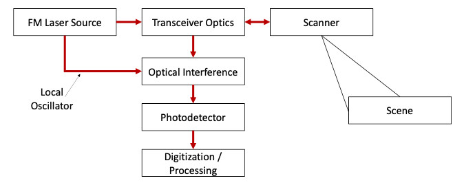
FM lidar uses coherent detection to measure the back reflected electric field by optically combining received light with a local copy of the laser source, the local oscillator (LO). This interferometric process produces electrical signals on a low cost, robust PIN photodiode. In contrast to direction detection, these signals are proportional to the product of the received electrical field with that of the LO. In addition to advantages outlined below, this leads to a high dynamic range measurement as coherent lidar photodetector signals scale as the square root of the back reflected signal power.
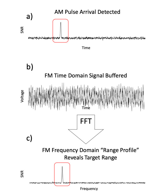
In both AM and FM lidar, the photodetector produces a time series of data for analysis. In the AM case, the time series can be analyzed serially in time to pick out the return ‘blip’ as a range measurement. In the FM case, the times series must be buffered for the duration of the measurement and then analyzed thereafter. Hundreds or thousands of time domain samples are stored, and then transformed into the frequency domain via a fast Fourier transform. The frequency domain is then searched for return ‘peaks.’
-
The detector signal for an AM system is serially analyzed as samples are digitized to detect an incoming pulse.
-
In an FMCW system, time domain sample must be collected and buffered.
-
An FFT reveals the frequency content of FMCW time domain samples. This frequency domain representation or “range profile” is then analyzed for peaks that indicate range to target and velocity.
When a laser beam from any lidar sensor (FM or AM) interacts with a moving object, the radial motion between target and sensor imparts a Doppler shift on the reflected light. An AM lidar’s direct receiver measures the reflected pulse but is unaware of the slight shift in wavelength. However, in an FM lidar’s coherent receiver, this Doppler shift surfaces as a measurable frequency difference between the reflected signal and the LO. Velocity is therefore measured in conjunction with range on every point in the point cloud. This leads to a more confident measurement of motion with microsecond latency. AM lidar systems must process point clouds over multiple frames to infer motion. This introduces noise and latency into motion estimation. While FM systems require more up-front signal processing as described above, there is less back-end processing on the data product to make it useful for perception. Inference is traded for measurement.

-
A set of range colored points show two pedestrians next to each other. Red is older, green is newer.
-
An angled view of age colored points shows these pedestrians passing. Velocity derivation of the pedestrians requires comparison of the points over time to infer motion.
-
Doppler colored points of a single FM lidar frame show pedestrian velocity on each data point. Limbs and torso motion are delineated.
Interference effects in lidar include solar or other background illumination sources and lidar-to-lidar effects. While lidar-to-lidar effects are of debatable significance, the effect of sunlight on lidar cannot be ignored as a mere ‘corner case.’ Consistent lidar operation in sunlight conditions should be considered mandatory. However, lidar sensors employing direct detection suffer from elevated detector noise when exposed to sunlight. Optical bandpass filters offer some mitigation, however, narrow-band operation across wide angle and wide temperature ranges are challenging to realize. Some sunlight will always get to the photodetector. In an AM system, high gain photodetectors are engineered to be sensitive to light. This underscores the problems with solar background elevating noise on the photodiode and limiting range performance.
In an FM system, solar background can reach the photodetector. However, solar radiation is not coherent with the LO. Therefore, the signal does not produce a frequency response within the RF band of interest for extraction of range and velocity measurements. The coherent detection process leads to stable performance in direct sunlight with no optical filters. As an analogy, the FM system is “tuned in” to a very narrow frequency channel and doesn’t “hear” other radio stations.

As stated above, FM signals are equivalent to the product of the reflected signal and LO electric fields. Therefore, a stronger LO will produce a stronger FM signal. This process is a form of optical amplification. The limit of this capability is the ‘shot noise’ or ‘quantum fluctuations’ driven by the LO on the photodetector. Shot noise limited performance is single-photon sensitive. This is important in the context of the interference rejection capability outlined above. High sensitivity with high selectivity allows long range performance with very low optical transmit powers. Since high optical power, even high peak power, is dangerous for photonic integrated circuits, the low-power capability enables chip-scale integration of FM lidar. Pulsed lidar systems, especially those at 1550nm, sometimes utilize large optical transmit power to achieve long range performance in the face of solar interference. This power is produced by expensive laser amplifiers that do not have an apparent chip-scale equivalent. In contrast, FM lidar utilizes transmit optical powers that can be produced in a semiconductor format.
The “magic” of coherent detection has long been recognized in DoD circles. However, intensive signal processing limited practical application for many decades to expensive defense programs or slow offline applications. The required data throughput and processing is indeed non-trivial. However, recent advances in FPGAs for telecommunications and radar signal processing have enabled low-cost FM lidar for autonomous driving perception.
Every lidar technology has challenges. But the processing requirements of FM lidar trade in the hardware challenges of AM systems for well-bounded signal-processing requirements. Replacing hardware pain with software gain is a powerful technology paradigm.
Stephen Crouch, co-founder and CTO for Blackmore Sensors and Analytics, Inc. has a decade of experience in coherent imaging, radar signal processing, and point cloud analysis. Stephen completed his thesis, "Synthetic Aperture LADAR Techniques," under Dr. Zeb Barber at Montana State University; he also has a Master of Science in Physics with a focus on Microelectronics and Photonics from Stevens Institute of Technology. He began his professional career as a radar systems engineer at Delphi.


