
Designing control systems with multiple motors
January 19, 2017

In recent years, technological progress has led to rapidly growing utilization of microcontrollers (MCUs) in a wide range of applications, including washing machines, air conditioners, and other...
In recent years, technological progress has led to rapidly growing utilization of microcontrollers (MCUs) in a wide range of applications, including washing machines, air conditioners, and other home appliances. These products strongly benefit from high efficiency and silent operation when being driven by modern motor control algorithms. The presence of an MCU also facilitates machine-to-machine communication for Internet of Things (IoT) applications, as well as control of the complete appliance. In general, manufacturers can deliver appliances offering higher efficiency, lower operational noise, and increased functional safety while still being cost effective.
Motor control can be a challenge for engineers developing modern appliances when several motors have to be controlled simultaneously. In addition to managing the increased complexity, engineers have to assure safe operation under all conditions, including appliance failure.
Consider the air conditioning system shown in Figure 1. Here, several motors have to be controlled. These include one or more fans in the indoor unit, the compressor, and one or more fans in the outdoor unit. All these motors have to operate efficiently, with low noise level, and be able to reliably detect failures such as over-current, over-heating, and mechanical defects to guarantee fail-safe operation.
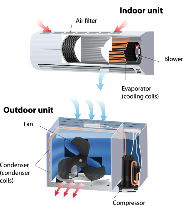
[Figure 1 | An air conditioning system has several motors, including one or more in the indoor unit, the compressor, and one or more in the outdoor unit.]
Optimized functionality
Figure 2 shows a vector control and field orientated control (FOC) algorithm commonly used for modern motor control of permanent magnet synchronous motors (PMSM). The blocks in light blue on the left side are implemented in software and include functionality such as coordinate transforms (Clarke, Park, and their inverse variants) and proportional, integral, derivative (PID) controllers, among others.

[Figure 2 | Inverter algorithm for AC motor control separated into software, internal, and external hardware blocks]
The internal hardware consists of dedicated microcontroller peripherals. This enables the efficient implementation of the software blocks. The analog-to-digital converter (ADC) is used to measure the current in the motor windings synchronized to the pulse width modulation (PWM), and feed them back to the control algorithm. The output of the control algorithm has to be brought to the power switches in the inverter, which uses PWM to drive the motor. This includes dead time insertion to cope with the limited switching speed of the power transistors.
An internal multi-function timer (MFT) generates not only the basic PWM pulses for each output phase (u, v, w), but also their complementary signals (u-, v-, w-), including dead time. These are used to drive the high and low side switches in the output bridge. In this example, an internal quadrature position and revolution counter (QPRC) peripheral is used to acquire rotor position information. Rotor information needed to execute the FOC algorithm is obtained from an optical or magnetic encoder often mounted on permanent-magnet synchronous motors (PMSMs) in industrial environments such as servo drives. In household and other applications, this block is typically implemented using sensorless control methods. Rather than measure rotor position, sensorless control calculates the rotor position from the measured motor currents using mathematical models of the motor.
When a single MCU is controlling multiple motors, performing these compute-intensive calculations efficiently and in real time requires a complex software structure that can be hard to develop, time-consuming to debug, and difficult to test to verify that the motor performs with the required level of quality and reliability. Integrated peripherals such as the MFT and QPRC simplify control of multiple motors by reducing the calculation load on the MCU.
Multiple MFTs allow the outputs for several motors to be generated by a single MCU. For example, the three MFTs integrated on the Cypress S6E2H High-Performance FM4 Family MCU allow the generation of up to 18 PWM channels (i.e., nine complementary pairs) to control three phase motors. Each MFT unit consists of three channels of free-run timer, six output compare units (OCUs), four input capture units, analog-to-digital converter (ADC) trigger units, and a waveform generator (WFG). In addition, the MFTs support emergency shutdown and a noise canceller unit.
An MFT generates a PWM waveform in several steps. The free-run timer provides the time base for PWM generation and defines the PWM resolution and frequency. The output compare units define duty cycle signals RT1, 3, 5 for each of the three output phases (note: only three output compare units are used in the example configuration shown in Figure 3). The waveform generator generates the corresponding complementary signals RTO0-RTO5, including automatically inserted dead time from the RT signals, which now can control power transistors such as FETs or insulated-gate bipolar transistors (IGBTs). The waveform generator also takes care that, in case of events like over-current due to a failure, the PWM can be immediately shut down. This is done without the need of software interaction and enables fail-safe operation.
The noise canceller unit in the waveform generator allows detection of only valid over-current events; i.e., it won’t trigger on short noise spikes. In case of such an over-current event, the waveform generator switches the MCU output pins from RTO0-RTO5 back to their normal GPIO function. This allows the desired fail-safe state to be defined (i.e., output high, output low, or high-Z) by pre-programming the corresponding registers during initialization. In addition to the hardware PWM shutdown, an interrupt can be generated to allow further fault handling at the application level.
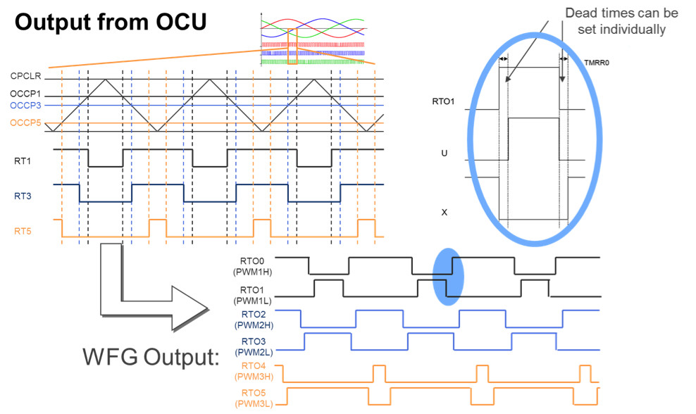
[Figure 3 | Generating PWM waveforms using a multi-function timer]
The QPRC plays an important role in motor control systems using quadrature encoders. A QPRC features three input channels – AIN, BIN and ZIN – for the two quadrature signals as well as an optional zero index signal. From these signals, the QPRC can detect the rotor position as well as rotation direction. An additional revolution counter is incremented or decremented after each rotation. This allows the absolute position to be calculated over multiple turns of the rotor. This is useful for applications such as linear drives, gearboxes, and other positioning applications.
Multi-motor design
Figure 4 shows the system block diagram of a modern air conditioning system. The outdoor unit contains the compressor and a fan, both controlled by separate FOC algorithms as described above to maximize efficiency. In addition, sensors measuring various quantities such as outside temperature are connected to the MCU. The connection between the outdoor and indoor units can be a simple serial protocol like UART or SPI.

[Figure 4 | System block diagram of modern air conditioning system controlling multiple motors]
In the indoor unit, one or more fans have to be controlled. These are controlled using an FOC algorithm to ensure silent operation and high efficiency. Several sensors measure room temperature, humidity, and other parameters. In addition to connecting to the outdoor unit, the indoor unit needs to integrate the air conditioner into the building management system (BEMS) for centralized heating, ventilation, and air conditioning (HVAC) control. This is done using a CAN interface.


